
Sterilization apparatus

Inactive Publication Date: 2003-03-25
MICROLIZER
View PDF10 Cites 12 Cited by
  • Summary
  • Abstract
  • Description
  • Claims
  • Application Information

AI Technical Summary

Benefits of technology

The object of the present invention is to provide a new and improved microwave sterilization apparatus, which sufficiently reduce or overcome the above-mentioned drawbacks of the known in the art sterilization apparatuses.
In particular the main object of the present invention is to provide a new and improved sterilization apparatus, enabling more efficient and fast sterilization.
The further object of the present invention is to provide a new sterilization apparatus, which is inexpensive and which has simple and compact construction.
The third object of the present invention is to provide a new and improved sterilization apparatus, which enables recycling of the air, exiting the apparatus and thus is environmentally friendly.

Problems solved by technology

Environmentally safe disposing of wastes is expensive measure, since relatively economical means like refusing, polygonal burial, incineration is either forbidden or are insufficiently safe.
The main disadvantage of the known in the art sterilization devices is associated with the fact, that they require excessive treatment time for completing the process.
The further disadvantage of the known sterilization devices is their relatively large size and complexity, and therefore inconveniency for use in small clinics and other medical institutions.
Still further disadvantage of the prior art sterilization devices lies in the fact, that they usually don't recycle the hot air releasing from the treatment chamber.
As a rule this air exits directly into atmosphere and since the exhausted air has been in direct contact with the wastes it pollutes the environment.

Method used


Image

  • Sterilization apparatus
  • Sterilization apparatus
  • Sterilization apparatus

Examples


Embodiment Construction

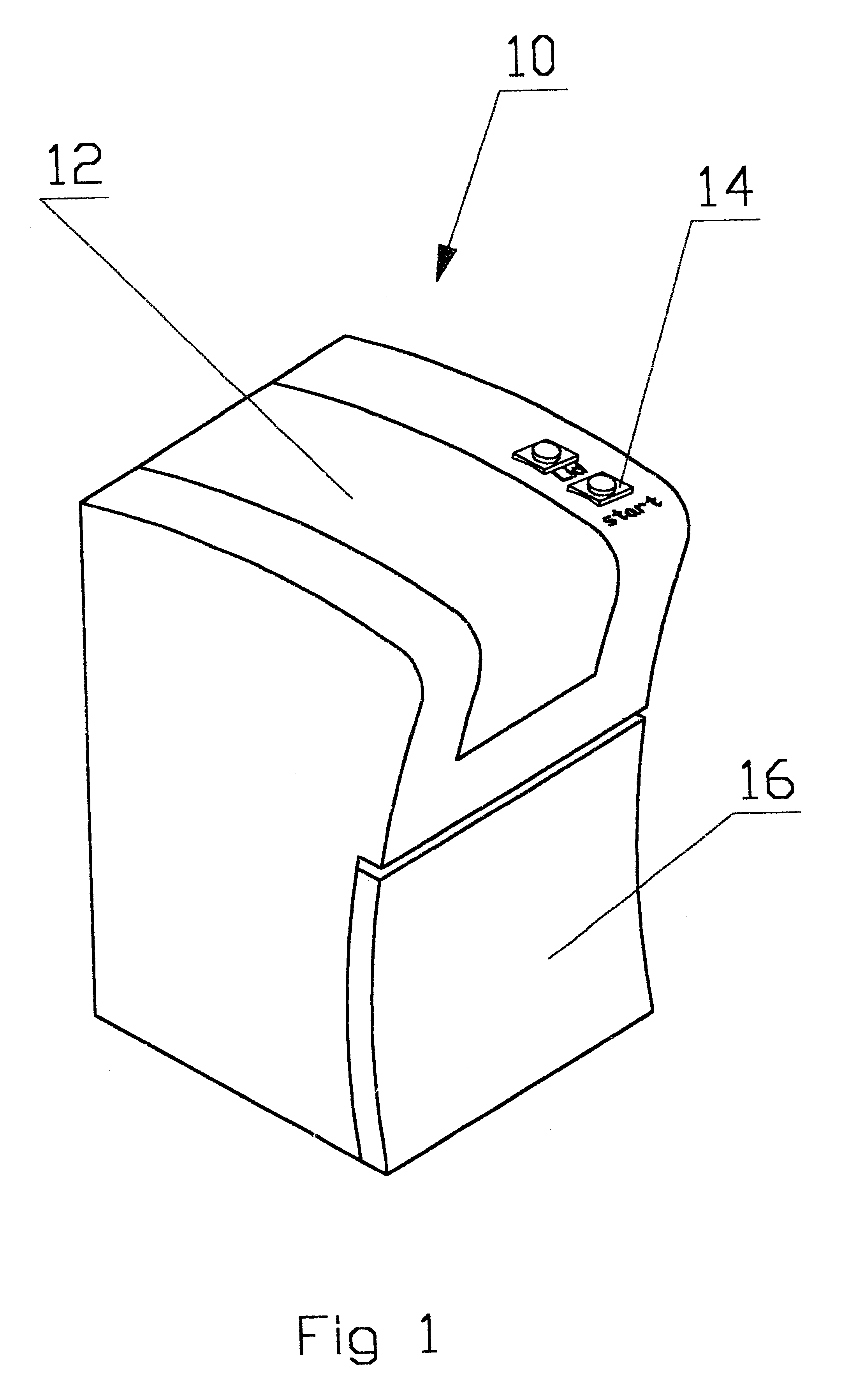
With reference to FIG. 1 the apparatus 10 of the invention comprises a housing configured substantially as a substantially parallelepiped box, having upper cover 12 with a main knob 14 for running the apparatus. Within the housing are mounted all the components of the apparatus. A front cover 16 mounted on the lower frontal side of the hosing enables access to the interior of the housing and evacuation of the treated wastes.

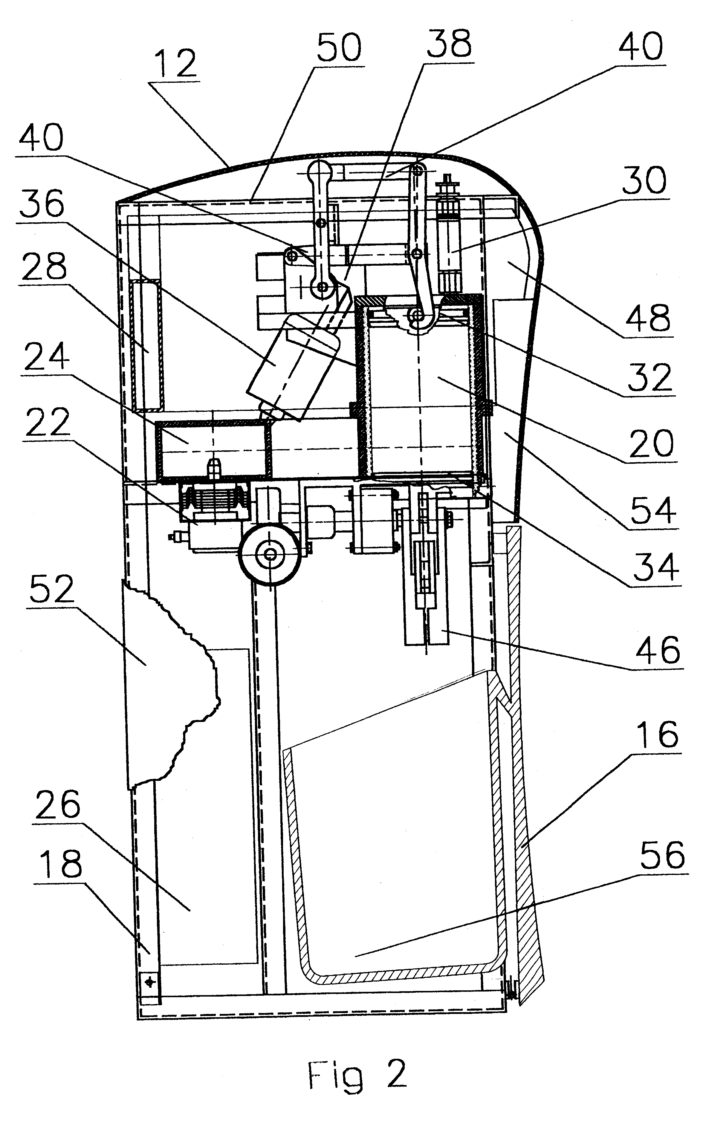
As seen in FIG. 2 within the housing resides a frame 18 carrying the main components of the apparatus. These components include a treatment chamber 20 for receiving medical wastes, a magnetron 22, a wave-guide 24 for directing the microwaves from the magnetron to the interior of the treatment chamber, a power supply 26, operatively coupled with the magnetron, a reservoir 28 for supplying a liquid fluid into the treatment chamber and a steam release valve 30, which controls the pressure within the chamber during the sterilization process. It is now shown specifica...


PUM

PropertyMeasurementUnit
Pressureaaaaaaaaaa
Transparencyaaaaaaaaaa
Energyaaaaaaaaaa

Abstract

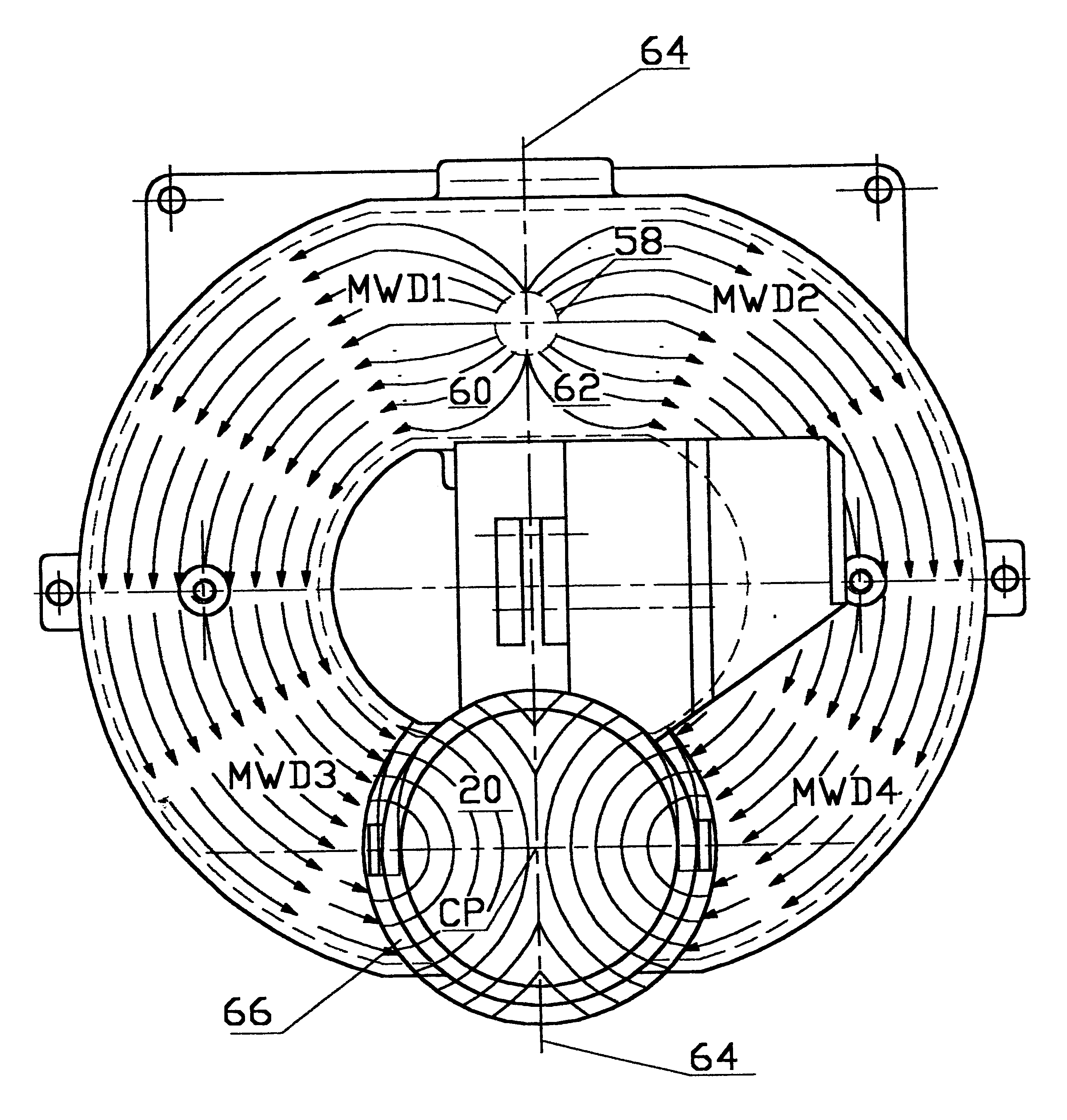
The present invention includes a method and apparatus for sterilization of medical wastes by exposing them to microwave energy. The microwaves are generated and directed through a wave-guide configured as a hollow duct, such that they are supplied to the interior of a treatment chamber from opposite directions causing their collision within the chamber.

Description

The present invention relates to sterilization of wastes, primarily to sterilization of medical wastes, e.g. bandages, needles, disposable syringes, gloves, test tubes, blades etc.More particularly the invention concerns sterilization treatment of wastes within a sealed container with the aim of microwave energy, produced by a magnetron source.It should be emphasized however, that the present invention is not limited strictly to the sterilization of medical wastes and it can be successfully employed in many other applications as well, in which sterilization treatment of wastes is required.Environmentally safe disposing of wastes is expensive measure, since relatively economical means like refusing, polygonal burial, incineration is either forbidden or are insufficiently safe.Therefore numerous devices for disinfection medical wastes have been devised for treatment of medical wastes locally. These devices employ various sources of energy for treatment and the further description will...

Claims


Application Information

Patent Timeline
IPC IPC(8): A61L11/00
CPCA61L11/00
Inventor MEDNIKOV, MARK
Owner MICROLIZER
Learn More