Structure of the front of a vehicle body

a technology for vehicle body and front part, which is applied in the direction of bumpers, vehicle components, pedestrian/occupant safety arrangements, etc., can solve the problems of air bag unexpected inflator, complex construction,

Inactive Publication Date: 2003-04-01
MAZDA MOTOR CORP
View PDF14 Cites 152 Cited by
  • Summary
  • Abstract
  • Description
  • Claims
  • Application Information

AI Technical Summary

Benefits of technology

to provide a simple and trouble-free structure of a front part of a vehicle body comprising a bumper which is associated with a lateral supporting member extending in the direction of vehicle width and an energy-absorbing member located ahead of the lateral supporting member, and a projecting part which is provided at a lower part of the bumper in such a manner that a forward end of the projecting part juts out more frontward than the lateral supporting member, whereby the projecting part sweeps legs of a pedestrian in the event of a collision between the vehicle and the pedestrian, causing the pedestrian to be thrown over toward the vehicle, and after the energy-absorbing member has absorbed impact energy exerted on the legs, the pedestrian is caused to drop onto the top of a hood and protected from secondary damage.

Problems solved by technology

When the bumper is so constructed, however, there has been a problem that it could be deformed even by a minor contact.
Although the aforementioned conventional system is advantageous in that it can provide increased safety of the pedestrian, it involves a complex construction due to the need for such obstacle sensing means as the ultrasonic sensor as well as the air bag.
In addition, the system is associated with the possibility of such malfunction that the air bag could unexpectedly inflate even when no collision has actually taken place.

Method used


Image

  • Structure of the front of a vehicle body
  • Structure of the front of a vehicle body
  • Structure of the front of a vehicle body

Examples


first embodiment

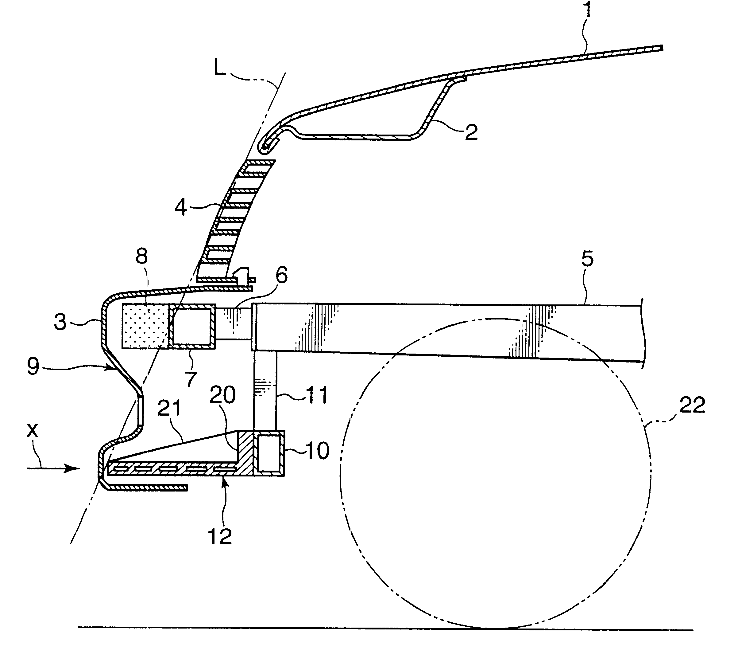
The structure of a front part of a vehicle body according to the invention is now described in detail with reference to the drawings. FIG. 1 shows the structure of the front part of the vehicle body which includes a hood 1 covering the top of an engine compartment.

The hood 1 is furnished with a hood reinforcement 2 as illustrated, and a radiator grille 4 is provided between a front lower part of the hood 1 and an upper part of a bumper face 3 which is made of resin.

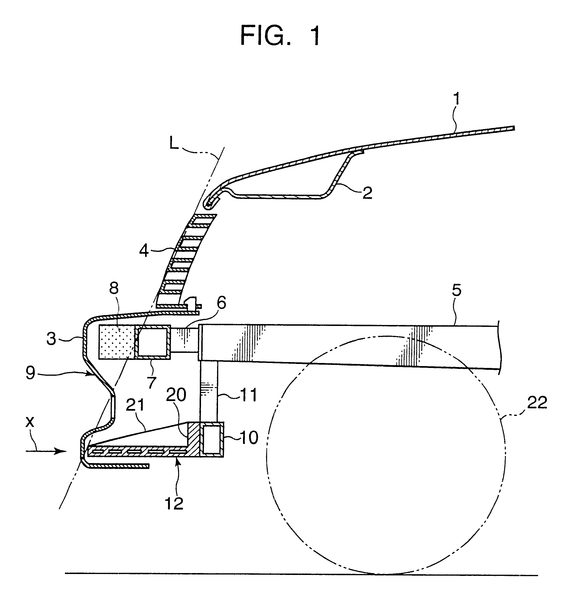
The vehicle structure includes left and right front side frame members 5 constituting part of a body frame which extends in a longitudinal direction of the vehicle, and a bumper reinforcement 7 is attached to forward ends of the front side frame members 5 via bumper brackets 6 as shown in FIGS. 1 and 2.

The bumper reinforcement 7 is a lateral supporting member extending in a lateral direction of the front part of the vehicle body. An energy absorber 8 is attached to the front of the bumper reinforcement 7 at the same heigh...

second embodiment

FIGS. 6 and 7 show the structure of a front part of a vehicle body according to the invention. Although the projecting part 12 is supported by its rear part by the front cross member 10 in the foregoing embodiment, there is provided a rectangular frame (reinforcing member) 23 which is secured at its both sides below the front side frame members 5 and, with a mounting plate 25 attached to front corners 23a of the rectangular frame 23 by set bolts 24, the rear part of the projecting part 12 is supported by the mounting plate 25 in the embodiment of FIGS. 6 and 7.

Since the structure of this embodiment is otherwise the same as the earlier-described first embodiment, elements identical to those included in the first embodiment are designated by the same reference numerals in FIGS. 6 and 7 and their detailed description is not given here. The projecting part 12 may be made of such synthetic resin as polypropylene (PP), polyethylene (PE) or nylon resin.

The structure of the second embodimen...

third embodiment

FIGS. 8 and 9 show the structure of a front part of a vehicle body according to the invention. Although the projecting part 12 is a resin member in the foregoing embodiments, a projecting part 28 of this embodiment is formed of a backing bar 26 which is a round-metal bar like an iron pipe extending along a lower part of the bumper face 3 and a pair of supporting arms 27 connecting the backing bar 26 to the front cross member 10 which is a structural member of the vehicle body.

Left and right ends of the backing bar 26 are curved or bent so that they are located slight rearward and the backing bar 26 matches the shape of the rear surface of the bumper face 3. Each of the supporting arms 27 is made by forming a piece of sheet metal into a gatelike cross-sectional shape having a top plate portion and left and right side plate portions. The thickness and cross-sectional area of the sheet metal are set to proper values to obtain the load characteristics "a" as depicted in FIG. 4.

The rear ...


PUM


Abstract

The invention provides a structure of a front part of a vehicle body that is simple and free from the risk of maloperation. In the event of a collision between the vehicle and a pedestrian, a projecting part sweeps the pedestrian by parts of his or her legs lower than the knees in the event of a collision between the vehicle and the pedestrian, causing the pedestrian to be thrown over toward the vehicle, and after an energy-absorbing member has absorbed impact energy exerted on the legs, the pedestrian is caused to drop onto the top of a hood and protected from secondary damage. In one specific example, a structure of a front part of a vehicle body in which a bumper (9) is provided at a lower front position of a hood (1) of the vehicle comprises a lateral supporting member (7) provided in the front part of the vehicle body and extending in the direction of vehicle width, an energy-absorbing member (8) provided ahead of the lateral supporting member (7), and a projecting part (12) provided at a lower part of the bumper 9 in such a manner that a forward end of the projecting part (12) juts out more frontward than the lateral supporting member (7).

Description

BACKGROUND OF THE INVENTION AND RELATED ART STATEMENT1. Field of the InventionThis invention relates to a structure of a front part of a vehicle body that is designed to provide enhanced safety to a pedestrian in the event of a collision between the vehicle and the pedestrian.2. Description of the Related ArtAn example of a conventionally known structure of this kind is found in Japanese Unexamined Patent Publication No. 11-1149, in which a bumper provided at the front of a vehicle body includes a bumper face, a foam material which serves as a shock-absorbing material, and a bumper reinforcement. To provide a sufficient shock-absorbing effect in the event of a collision between the vehicle and a pedestrian with this structure, it has been necessary to construct the bumper such that the bumper face would easily deform on impact. When the bumper is so constructed, however, there has been a problem that it could be deformed even by a minor contact.To provide a solution to the aforement...

Claims


Application Information

Patent Timeline
Patent Type & Authority Patents(United States)
IPC IPC(8): B60R19/18B60R19/24B60R19/34B60R19/12B60R19/00B60R19/32B60R21/34
CPCB60R19/12B60R19/32B60R19/34B60R2019/1886B60R2019/1813B60R2019/1866B60R2019/1873B60R21/34B60R19/00
Inventor IWAMOTO, TATSUHIKOFURUMOTO, ARIHIROTSUKIJI, YUTAKAHARA, MASAOMATSUDA, YUSHIADACHI, DAISABUROUOGAWA, MASANORINAKAMAE, TAKAYUKITERADA, SAKAYUKONDOU, KAZUMA
Owner MAZDA MOTOR CORP
Why Eureka
Try Eureka