Systems and methods for stitching overlapping swaths

Inactive Publication Date: 2003-04-01
XEROX CORP
View PDF3 Cites 52 Cited by
  • Summary
  • Abstract
  • Description
  • Claims
  • Application Information

AI Technical Summary

Problems solved by technology

Thus, the fluid ejection system's productivity is limited to the size of the fluid ejectors used.
However, pattern quality of the ejected fluid when using this process is reduced as the opportunity to place fluid drops in a given location is limited to one pass of the fluid ejector.
Another problem occurs in that stitch errors occur between each swath as the ejected drops in a first swath fail to align with the ejected drops in adjacent second swath.
The stitch errors can occur whenever a subsequent drop ejected by the fluid ejector in one swath is disp

Method used


Image

  • Systems and methods for stitching overlapping swaths
  • Systems and methods for stitching overlapping swaths
  • Systems and methods for stitching overlapping swaths

Examples


Example

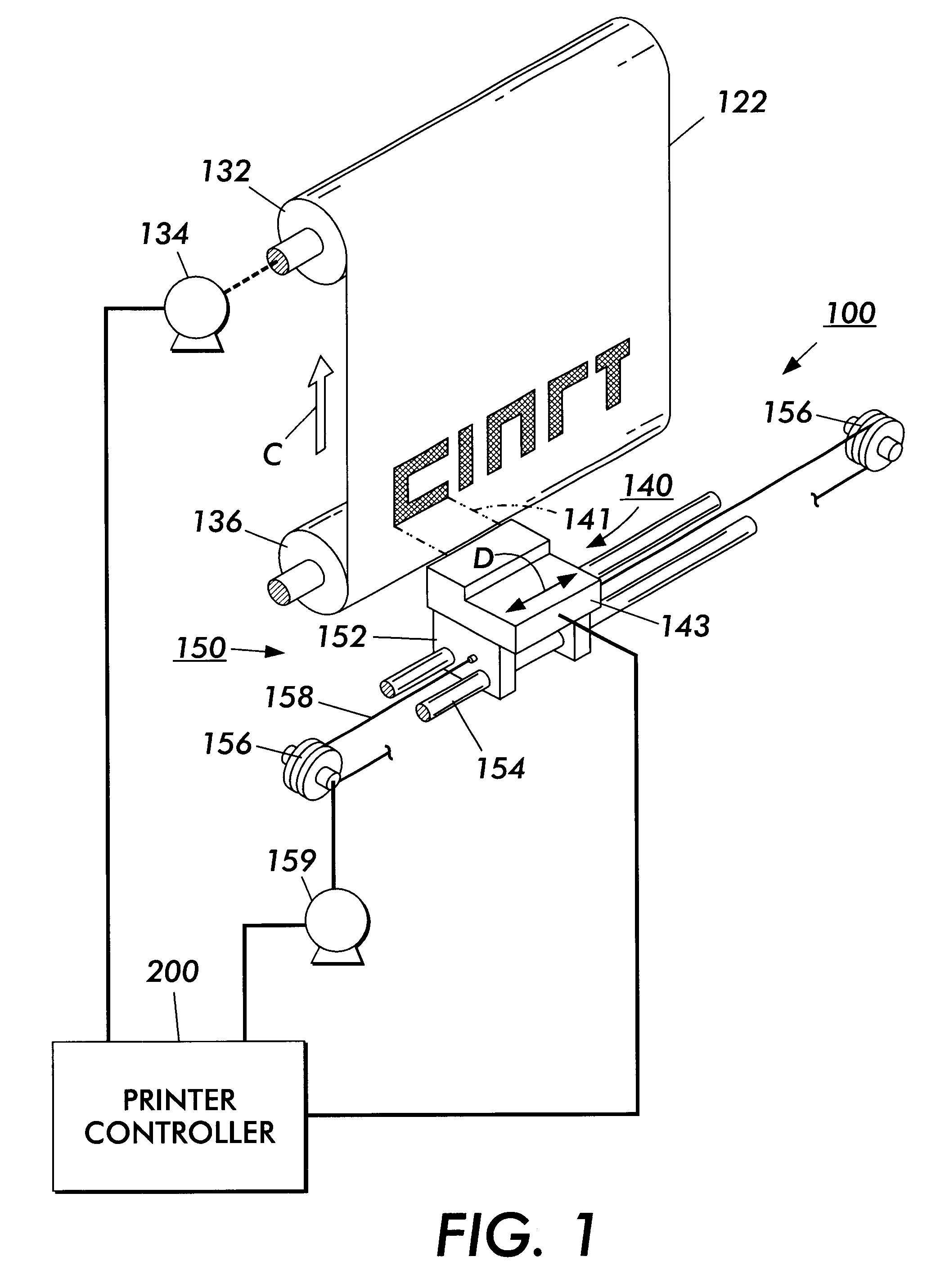
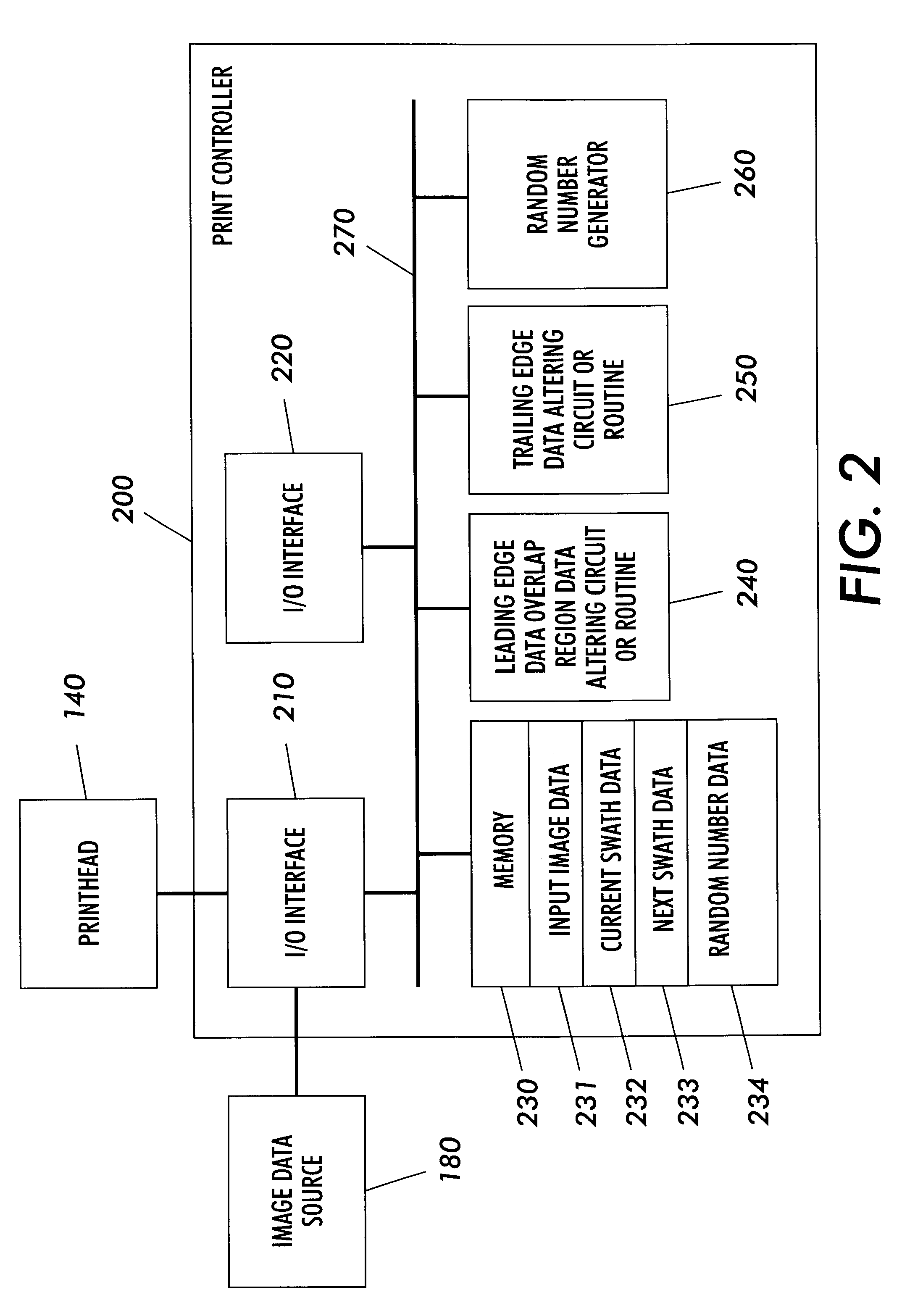
For simplicity and clarification, the operating principles and design factors of various exemplary embodiments of the systems and methods according to this invention are explained with reference to one exemplary embodiment of a carriage-type ink jet printer 100, as shown in FIG. 1, and one exemplary embodiment of a printhead 140, as shown in FIG. 2. The basic explanation of the operation of the ink jet printer 100 and the printhead 140 is applicable for the understanding and design of any fluid ejection system that incorporates this invention. Although the systems and method of this invention are described in conjunction with the ink jet printer 100 and the printhead 140, the systems and methods according to this invention can be used with any other known or later-developed fluid ejection system.

FIG. 1 is a schematic view of one type of ink jet printer 100 usable with the stitching systems and methods according to this invention. As shown in FIG. 1, a carriage-type ink jet printer 1...


PUM


Abstract

System and methods for using a fluid ejection system to distribute fluid drop density of a region between at least two overlapping swaths having pixels on a receiving medium. Using the method, overlapping swaths are stitched together by distributing a fluid ejection pattern between the overlapping swaths within the overlapped region. Because small drops of fluid can be distributed within a single region, the fluid ejection pattern can be controlled and intermediate density regions can be created by distributing the fluid of drops within a region between two fluid ejector heads or between two swaths of the same fluid ejector head. The distribution can be linear or non-linear. Furthermore, overlapping swaths are stitched together by randomly varying a stitch location within the overlapped region. In this case, a stitch location is randomly varied in the slow scan direction.

Description

1. Field of InventionThis invention relates to fluid ejection systems and methods.2. Description of Related ArtFluid ejection systems, such as ink jet printers, have at least one fluid ejector that directs droplets of fluid towards a receiving medium. Within the fluid ejector, the fluid may be contained in a plurality of channels. Energy pulses are used to expel the droplets of fluid, as required, from orifices at the ends of the channels.A carriage-type thermal fluid ejector system is described in U.S. Pat. No. 4,638,337 ('337 Patent). The system disclosed in the '337 patent has a plurality of printheads, each with its own fluid tank cartridge, mounted on a reciprocating carriage. The channel nozzles in each fluid ejector are aligned perpendicular to the line of movement of the carriage. A swath of information is printed on a stationary receiving medium as the carriage is moved in one direction. The receiving medium is then stepped, perpendicular to the line of carriage movement, b...

Claims


Application Information

Patent Timeline
IPC IPC(8): B41J11/42B41J2/01B41J2/205
CPCB41J11/42G06K15/105G06K2215/111
Inventor NYSTROM, PETERCELLURA, MARKWALSH, JOHN
Owner XEROX CORP
Why Eureka
Try Eureka