
Systems and methods for adjusting lighting of a part based on a plurality of selected regions of an image of the part

Inactive Publication Date: 2003-04-01
MITUTOYO CORP
View PDF32 Cites 325 Cited by
  • Summary
  • Abstract
  • Description
  • Claims
  • Application Information

AI Technical Summary

Benefits of technology

This invention separately provides systems, methods and graphical user interfaces that allow a user to easily and quickly define multiple regions of interest that can be used to determine the image quality of a captured image.

Problems solved by technology

Without adequate standardization and repeatability, archived programs vary in performance over time and within different instruments of the same model and equipment.
However, even if the output light intensity of the light source is controlled to a particular command level, the resulting image captured by the machine vision system may not have a desired image quality or characteristic.
Again, even though the output light intensity may be at the desired value, the image quality or characteristic of the resulting captured image may be insufficient.
Moreover, the output light intensity can not be measured directly by the user.
This inconsistency of the lighting behavior makes it difficult to correctly run part-programs even within a single run of parts on a single machine.
As a result, because the brightnesses of resulting images generated when viewing different parts are often different, part programs do not run consistently.

Method used


Image

  • Systems and methods for adjusting lighting of a part based on a plurality of selected regions of an image of the part
  • Systems and methods for adjusting lighting of a part based on a plurality of selected regions of an image of the part
  • Systems and methods for adjusting lighting of a part based on a plurality of selected regions of an image of the part

Examples


Embodiment Construction

The lighting adjusting systems, methods and graphical user interfaces of this application are useable in conjunction with the lighting calibration systems and methods disclosed in the U.S. patent Ser. No. 09 / 425,990, herein incorporated by reference in its entirety.

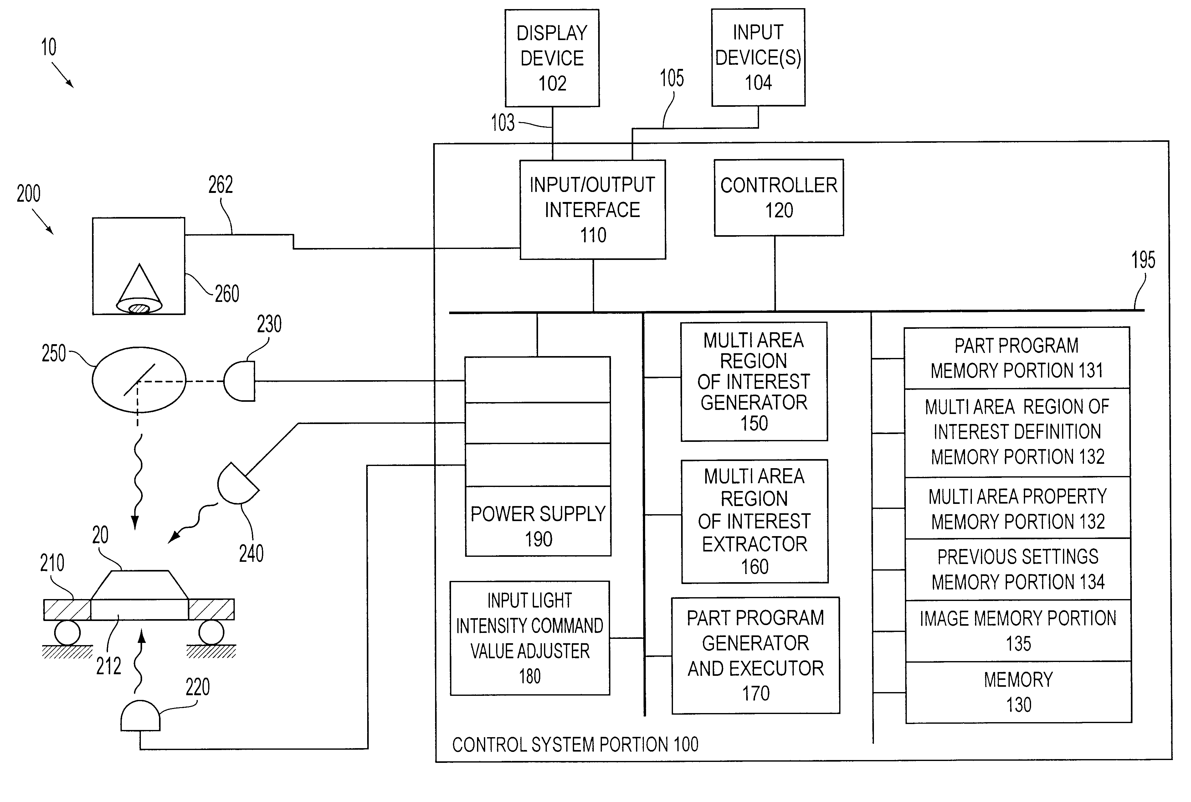
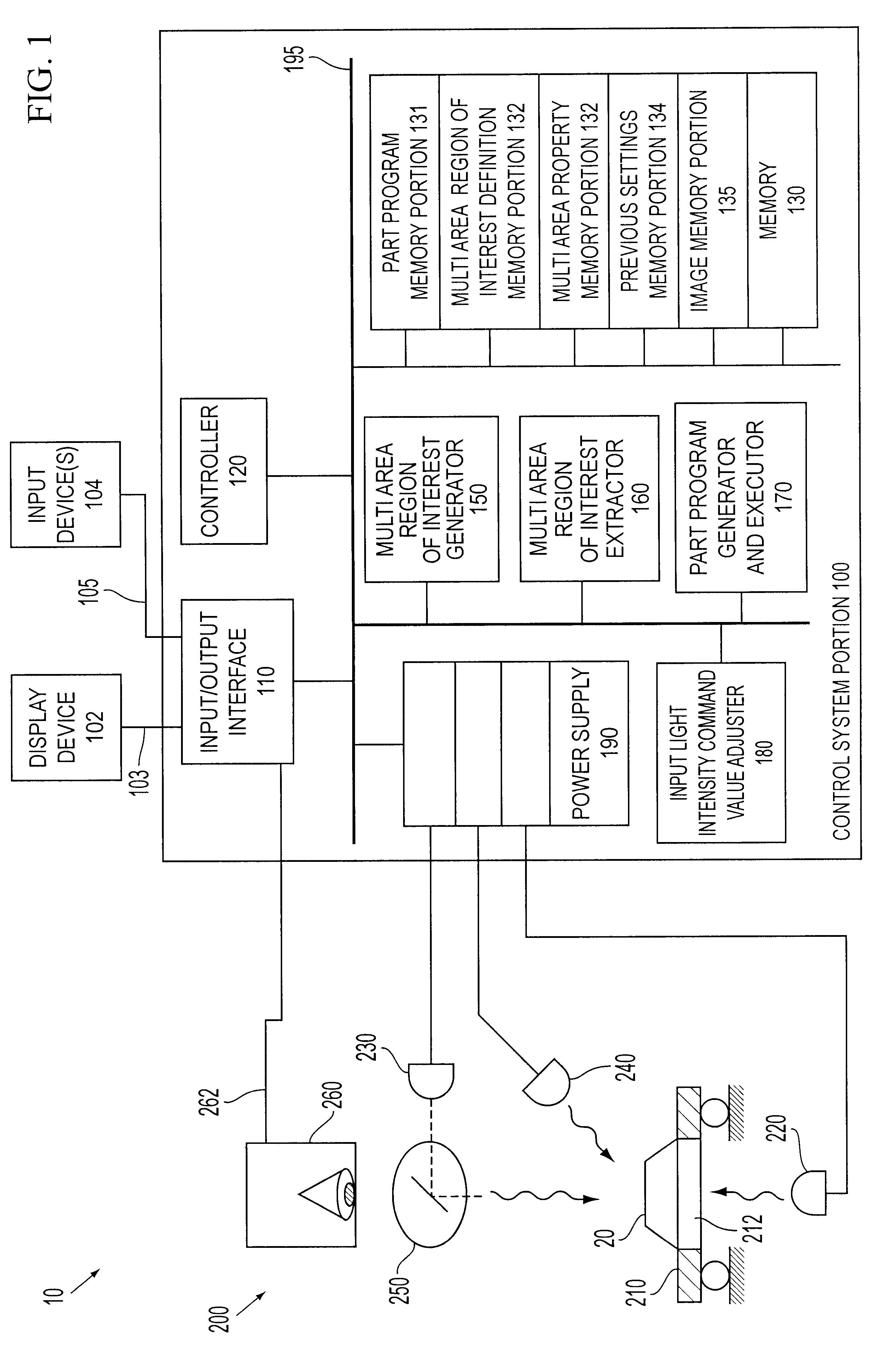
For simplicity and clarification, the operating principles, and design factors of this invention are explained with reference to one exemplary embodiment of a vision system according to this invention, as shown in FIG. 1. The basic explanation of the operation of the vision system shown in FIG. 1 is applicable for the understanding and design of any vision system that incorporates the lighting adjusting systems and methods according to this invention.

As used herein, the input light intensity command value is the light intensity value set by the user to control the light output intensity of the source light. The input light intensity command value is set either expressly in a part program or using a user interface. The ran...


PUM


Abstract

The lighting behavior of a vision system is inconsistent between vision systems, within a vision system over time or between parts being viewed. This inconsistency makes it difficult to correctly run part programs even within a single run of parts on a single machine. The multi area image quality tool systems, methods and graphical user interfaces adjust the light intensity of a vision system to obtain a desired image quality or characteristic of a captured image. The multi area image quality tool is used to define a plurality of regions of interest within a captured image to be used to determine the image quality or characteristic of the captured image resulting from a current illumination level. The multi area image quality tool allows a user to easily and quickly define multiple regions of interest that can be used to determine the image quality of a captured image. The multi area image quality tool allows the user to specify the location, orientation and size of two or more regions of interest around a critical feature of the captured image, and to specify the light sources to be used to illuminate the part, the image quality to be measured, and a range of acceptable values for that image quality. Portions of the image are extracted based on the defined regions of interest. The image quality of the captured image is determined based on an analysis of the regions of interest and the image quality defined in the multi area image quality tool.

Description

1. Field of the InventionThis invention relates to lighting systems for vision systems.2. Description of Related ArtThe light output of any device is a function of many variables. Some of the variables include the instantaneous drive current, the age of the device, the ambient temperature, whether there is any dirt or residue on the light source, the performance history of the device, etc. Machine vision instrument systems typically locate objects within their field of view using methods which may determine, among other things, the contrast within the region of interest where the objects may be found. To some degree, this determination is significantly affected by the amount of incident light or transmitted light.Automated video inspection metrology instruments generally have a programming capability that allows an event sequence to be defined by the user. This can be implemented either in a deliberate manner, such as programming, for example, or through a recording mode which progr...

Claims


Application Information

Patent Timeline
IPC IPC(8): H04N5/235G01N21/88
CPCH04N5/2354G01N21/8806H04N23/74
Inventor WASSERMAN, RICHARD M.TESSADRO, ANA M.
Owner MITUTOYO CORP
Learn More