AI technical title is built by PatSnap AI team. It summarizes the technical point description of the patent document.
a liner system and wellbore technology, applied in the direction of directional drilling, water installations, borehole/well accessories, etc., can solve the problems of damage to the lateral liner and the inability to re-establish the pathway through the main wellbore, and achieve the effect of facilitating movemen
Inactive Publication Date: 2003-04-15
WEATHERFORD TECH HLDG LLC
View PDF86 Cites 19 Cited by
Summary
Abstract
Description
Claims
Application Information
AI Technical Summary
This helps you quickly interpret patents by identifying the three key elements:
Problems solved by technology
Method used
Benefits of technology
Benefits of technology
In one aspect such a system has a plurality of spaced-apart coupling bushings disposed above the lateral bore which serve to position the milling system and prevent it from entering the lateral liner. Such coupling-bushing will facilitate directing of the milling system in the direction of the main wellbore so that the milling system mills through the liner in the direction of the main wellbore, thereby re-establishing the main wellbore. In one aspect one of the coupling bushings is placed above, and in one aspect near the top of, the window at the beginning of the lateral bore.
In some systems a lateral bore liner is supported by an external casing packer, liner hanger, pack-off liner hanger, or similar support positioned in a main wellbore. A milling system as described above that is introduced into the liner through the main wellbore should not abut or hang up on the top of the support apparatus. To facilitate movement of such a milling system past and through an external casing packer a centering apparatus is releasably connected at the bottom of the milling system. As the milling system approaches the top of the external casing packer, the centering device contacts the top of the external casing packer with the lower end of the milling system centered over the bore into the liner. Further downward force on the string to which the milling system is attached releases the centering device and the milling system enters the liner.
Such systems and methods with a centering device releasably connected to the milling system for facilitating its entry into a top opening of a liner in the main wellbore.
Problems solved by technology
Without such a guide a lateral liner can be damaged by the wrongly located milling system, and the pathway through the main wellbore will not be re-established.
Method used
Image
Click on the blue label to locate the original text in one second.
Reading with bidirectional positioning of images and text.
Examples
Embodiment Construction
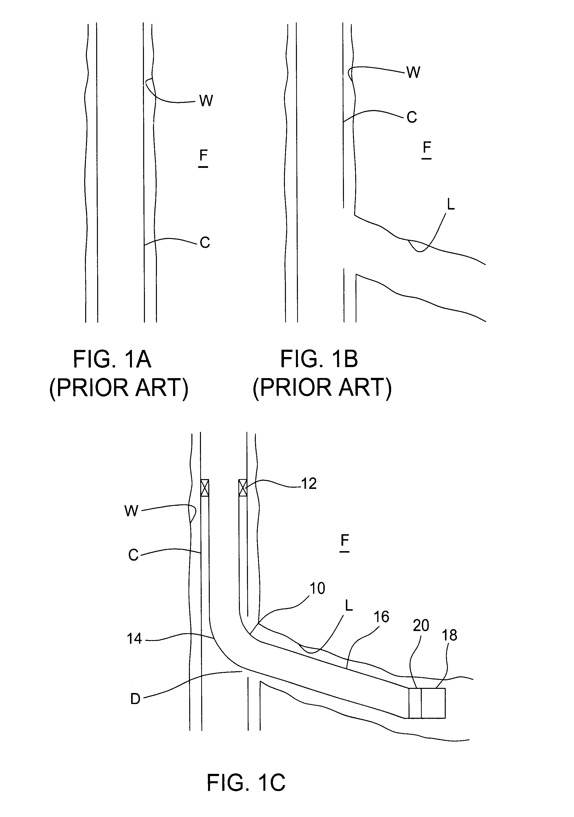
Referring now to FIG. 1A, a main wellbore W extends down into an earth formation F and is cased with a string of casing C. Such wellbores and the drilling of them are old and well-known, as are the systems, tubulars, and methods for casing them.
FIG. 1B shows the results of well-known window milling methods that have created a window D and well-known drilling methods that have produced a lateral bore L.
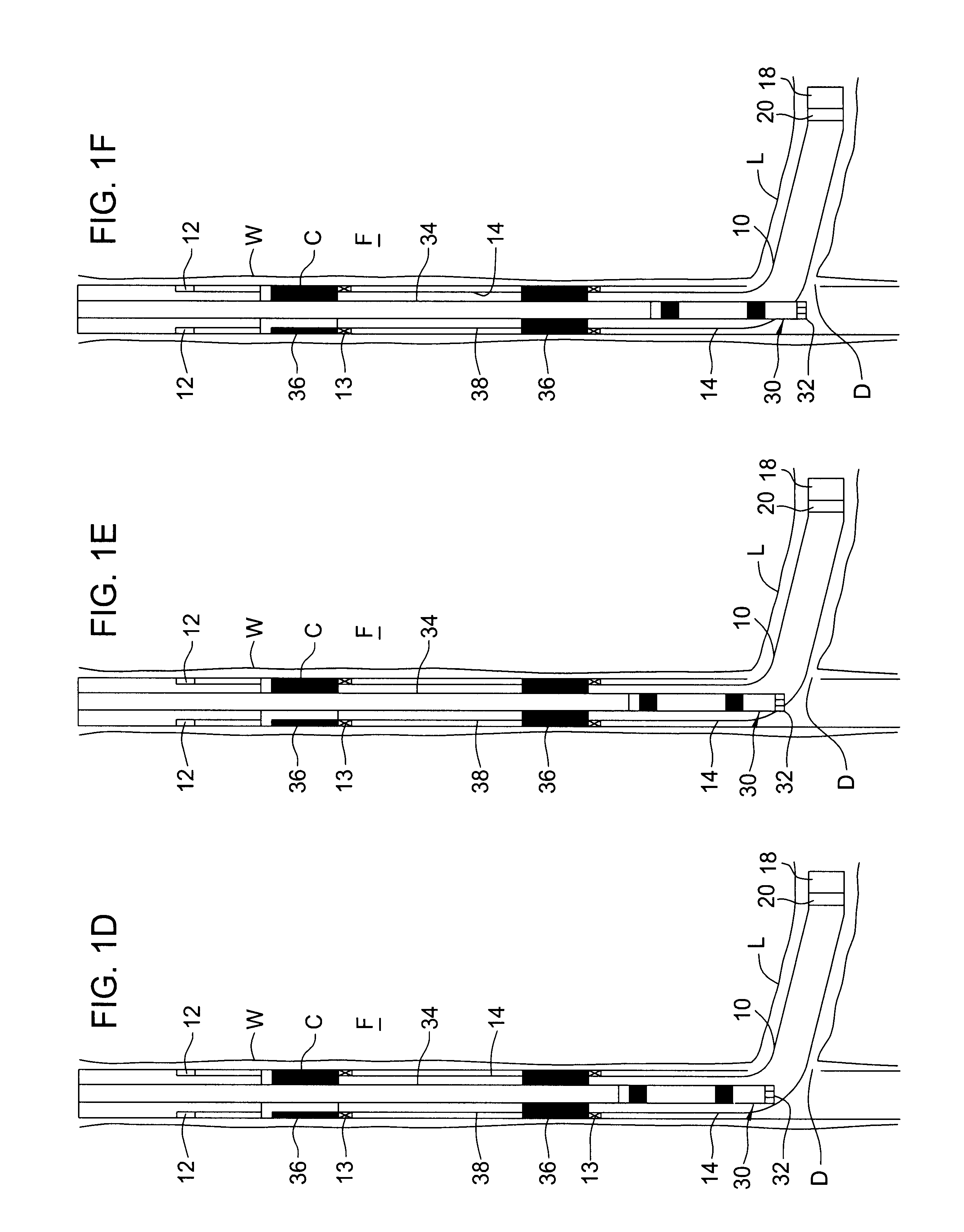
FIG. 1C shows a liner assembly 10 according to the present invention installed in part of the main wellbore W and part extending into the lateral bore L. It is within the scope of this invention for the part of the liner assembly 10 to extend to any desired length into the lateral base L, including substantially all of the length of the lateral bore L.
A suitable support 12 holds the liner assembly 10 in place. In one aspect, the support 12 is an external casing packer, but it is within the scope of this invention for it to be a liner hanger, tubing hanger, pack off or any support that ...
PUM
Abstract
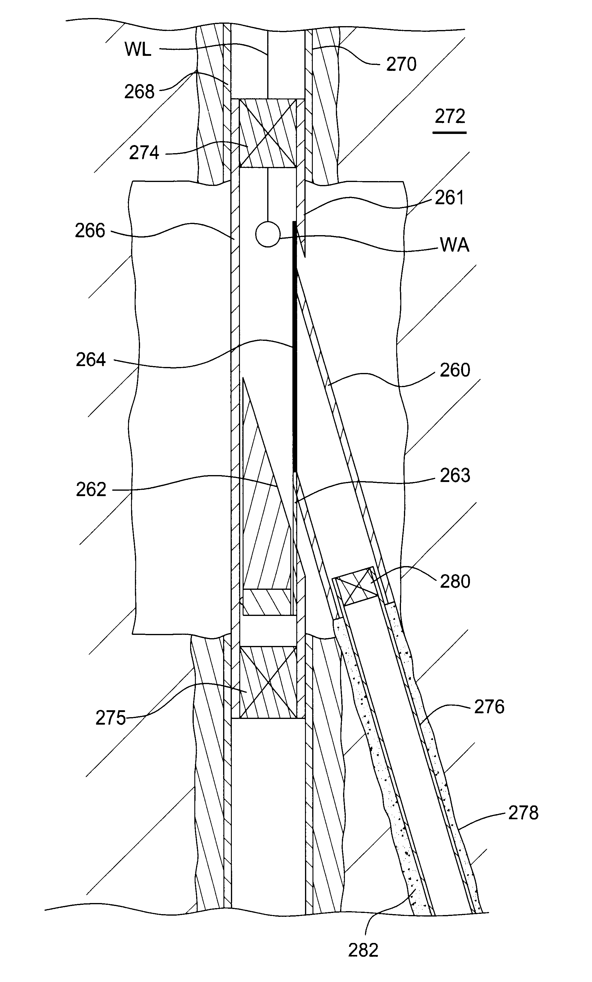
Wellbore apparatus has been invented which, in at least certain aspects, includes a wellbore apparatus having a tubular member with a top end, a bottom end, a hollow portion, and a window therethrough, a sleeve positioned within the hollow portion of the tubular member, the sleeve having a top end and a bottom end, a diverter apparatus within or outside the tubular member amd, optionally, below the bottom end of the sleeve, the sleeve movable so that the diverter, and the diverter directs the sleeve to the window and through the window into a bore extending beyond the window, and the window having an edge therearound to which the top end of the sleeve is weldable to sealingly secure the sleeve at the window.
Description
1. Field of the InventionThis invention is directed to wellbore milling systems and methods; and, in one particular aspect, to such systems and methods for milling through a liner that projects into a lateral wellbore from a main wellbore to re-establish a pathway to the main wellbore.2. Description of Related ArtThe prior art discloses a wide variety of wellbore milling systems and methods and a wide variety of systems and methods for re-establishing a pathway through a main wellbore after lining a lateral wellbore with a liner. Many such prior art systems and methods require a guide for a milling system so that the milling system mills back through the liner rather than entering the liner itself and milling in the wrong location. Without such a guide a lateral liner can be damaged by the wrongly located milling system, and the pathway through the main wellbore will not be re-established.SUMMARY OF THE PRESENT INVENTIONThe present invention, in one aspect, discloses a milling syste...
Claims
Application Information
Patent Timeline
Application Date:The date an application was filed.
Publication Date:The date a patent or application was officially published.
First Publication Date:The earliest publication date of a patent with the same application number.
Issue Date:Publication date of the patent grant document.
PCT Entry Date:The Entry date of PCT National Phase.
Estimated Expiry Date:The statutory expiry date of a patent right according to the Patent Law, and it is the longest term of protection that the patent right can achieve without the termination of the patent right due to other reasons(Term extension factor has been taken into account ).
Invalid Date:Actual expiry date is based on effective date or publication date of legal transaction data of invalid patent.
InventorKUCK, MARCBAILEY, THOMAS FLOYDJOHNSON, MONTE IRAROBERTSON, ROBERT EUGENEBARRY, ANDREW ARTHURCARTER, THURMAN JAMESBLIZZARD, JR., WILLIAM ALLENSINGLETON, TEME FORRESTROBERTS, JOHN DOUGLASSPIELMAN, WILLIAM ALANHAUGEN, DAVID MICHAELMCCLUNG, III, GUY LAMONTE

