Door lock drive unit

Inactive Publication Date: 2003-05-06
DENSO CORP
View PDF8 Cites 51 Cited by
  • Summary
  • Abstract
  • Description
  • Claims
  • Application Information

AI Technical Summary

Benefits of technology

As described above, a unlatch mechanism and a closing mechanism, in which unlatch operation and closing operation are separately conducted by the normal and the reverse rotation of the gear unit, are provided. Even in the middle of a closing operation conducted by the reverse rotation of the gear unit, the closing operation is stopped (The motor is stopped.), and then, when the motor is normally rotated, it is possible to change over from the stopping position of the closing operation to the unlatch operation (door opening operation). Due to the foregoing, it is possible to reduce the size of a door lock drive unit capable of conducting both the unlatch function and the closing function by one motor and, further, safety can be ensured in the case of an emergency in which a finger is pinched.

Problems solved by technology

If the closing operation is conducted quickly, the following problems may be encountered.

Method used


Image

  • Door lock drive unit
  • Door lock drive unit
  • Door lock drive unit

Examples


first embodiment

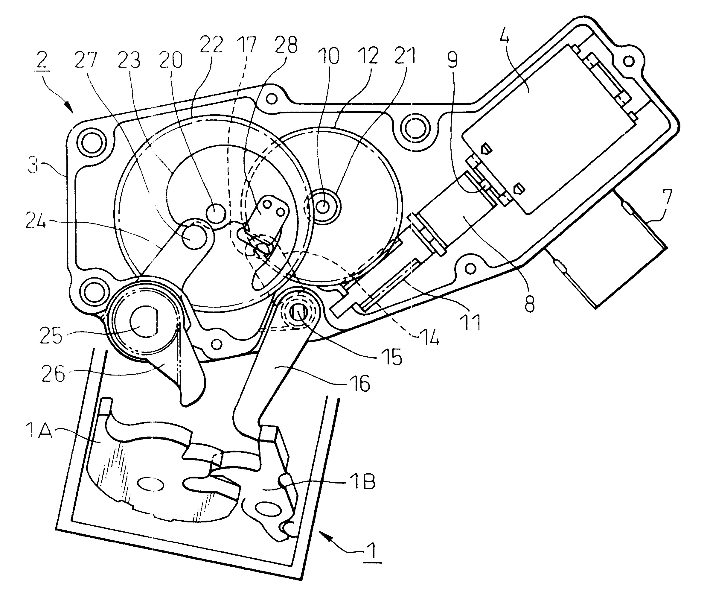
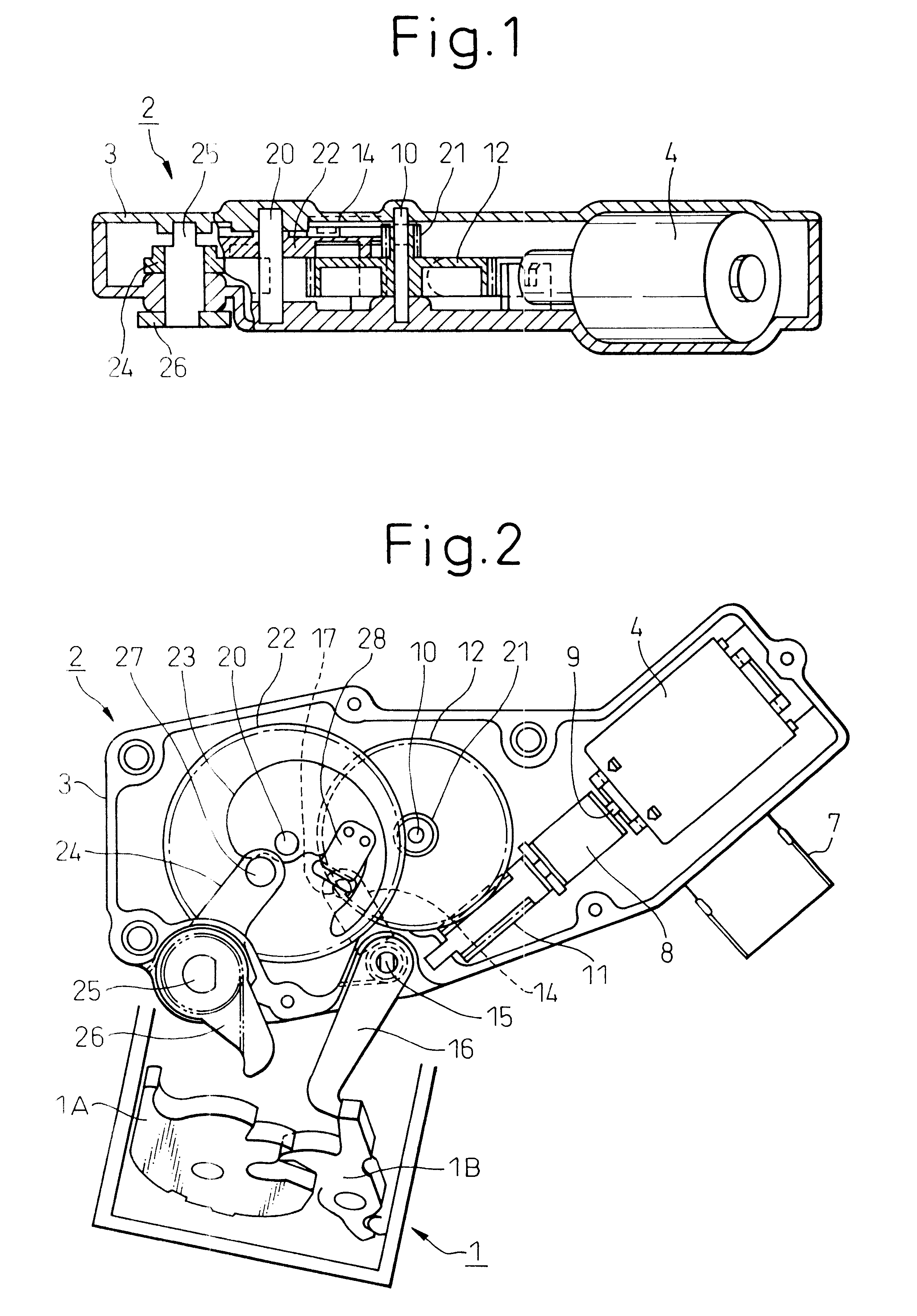
Referring to the accompanying drawings, a door lock drive unit of the first embodiment of the present invention will be explained in detail. In this connection, in the door lock drive unit explained below, the structure of the closing and unlatch actuator is devised, so that one motor can perform both the unlatch function and the closing function, and further while the size of the door lock drive unit is reduced, safety can be ensured in the case of an emergency in which a finger is pinched.

FIGS. 1 and 2 are views showing a structure of the closing and unlatch actuator 2 of the first embodiment of the present invention. The door lock drive unit used for a vehicle such as an automobile of the present embodiment includes: a door lock 1 to keep a door of a vehicle such as an automobile closed; a closing and unlatch actuator 2 containing both the unlatch mechanism for releasing an engagement mechanism of the door lock 1 and the closing mechanism for operating a latch from a half latch s...

second embodiment

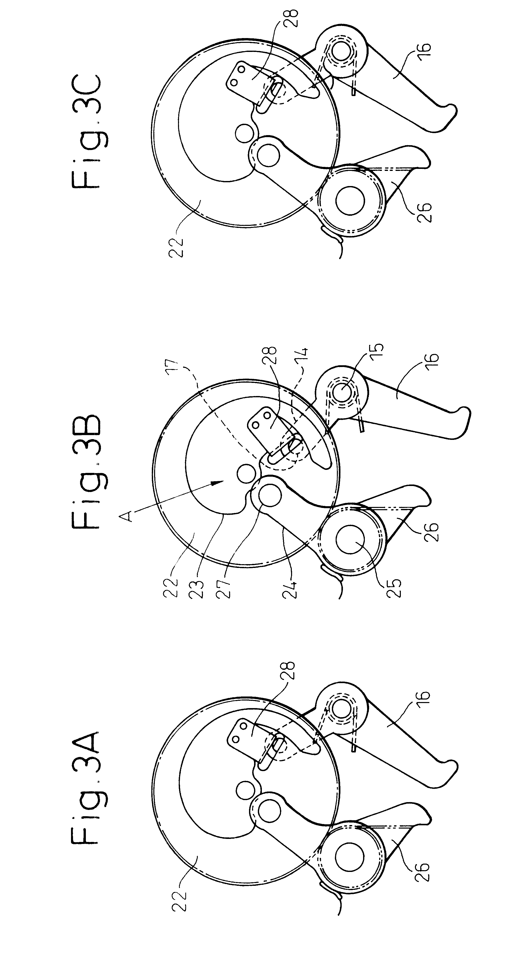
The door lock drive unit of the second embodiment of the present invention is shown in FIGS. 9, 10 and 11. FIG. 9 is a plan view showing a structure of the closing and unlatch actuator 2 which is the second embodiment of the present invention. FIGS. 10 and 11 are schematic illustrations for explaining the operation of the closing and unlatch actuator 2. Like reference characters are used to indicate like parts in the first and the second embodiment, and the explanations are omitted here. In this connection, the door lock drive unit of the second embodiment explained below is different from that of the first embodiment in the following points. The arrangement of the first operation lever 14, second reduction gear 2 and engagement member 28 shown in the first embodiment is changed from that of the first embodiment, so that the degree of freedom of designing the closing and unlatch actuator 2 is enhanced and the structure is simplified.

As shown in FIG. 9, the output cam 23 is integrall...


PUM


Abstract

A rotating speed of the motor 4 is reduced at a high reduction ratio by using a reduction gear (the first and the second reduction gear), and the unlatch mechanism for conducting unlatch operation of the door lock 1 and the closer mechanism for conducting closer operation of the door lock 1 are separated from each other by the normal and the reverse rotating direction of the second reduction gear. Due to the foregoing, even in the middle of a closing operation conducted by the reverse rotation of the second reduction gear, when the closing operation is stopped and then the motor 4 is normally rotated, it is possible to switch from the stopping position of the closing operation to unlatch operation.

Description

1. Field of the InventionThe present invention relates to a door lock drive unit. More particularly, the present invention relates to a door lock drive unit in which an unlatch mechanism for releasing a door lock engagement mechanism and a closing mechanism for closing a latch from a half latch state to a full latch state are composed of one motor.2. Description of the Related ArtConventionally, there is provided a door lock drive unit for vehicle use in which one motor conducts an unlatch function to unlatch a latch from a door closing state to an unlatch state by rotating the motor normally and also conducts a closing function to close the latch from an incomplete door closing state (half latch state) to a door closing state (full latch state) by reversing the motor.The door lock drive unit must have a large-ratio reduction gear which is housed in an actuator and conducts a closing function using a drive force generated by a motor because it is necessary to provide a large torque ...

Claims


Application Information

Patent Timeline
Patent Type & Authority Patents(United States)
IPC IPC(8): E05B65/12E05B17/22E05B17/00E05B85/24B60J5/00E05B47/00E05B81/06E05B81/16E05B81/34
CPCE05B81/14E05B81/20E05B81/64E05B81/21Y10S292/23Y10T292/1047Y10T292/1082E05B47/00
Inventor AMANO, HITOSHI
Owner DENSO CORP
Why Eureka
Try Eureka