
Imaging apparatus, strobe device, and charging-control method

a technology of strobe device and charging control, which is applied in the direction of electric variable regulation, process and machine control, instruments, etc., can solve the problems of difficulty in limiting a power supply, and achieve the effect of preventing the heat generation of the switching element and ensuring safety

Inactive Publication Date: 2011-03-29
SONY CORP
View PDF7 Cites 3 Cited by
  • Summary
  • Abstract
  • Description
  • Claims
  • Application Information

AI Technical Summary

Benefits of technology

[0017]In view of the above-mentioned subject, it is desirable to provide an imaging apparatus including a strobe device having a charging circuit with safety improved for a case where an abnormal current flows through a switching element, a strobe device, or a charging-control method.
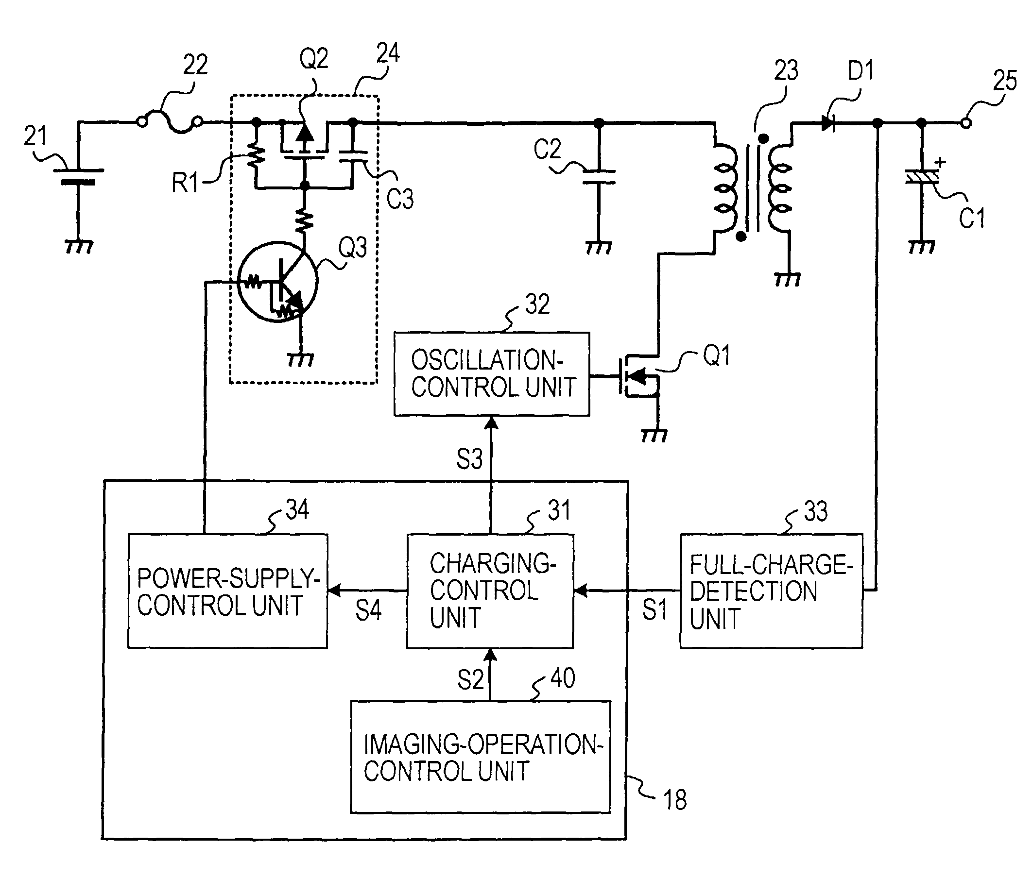
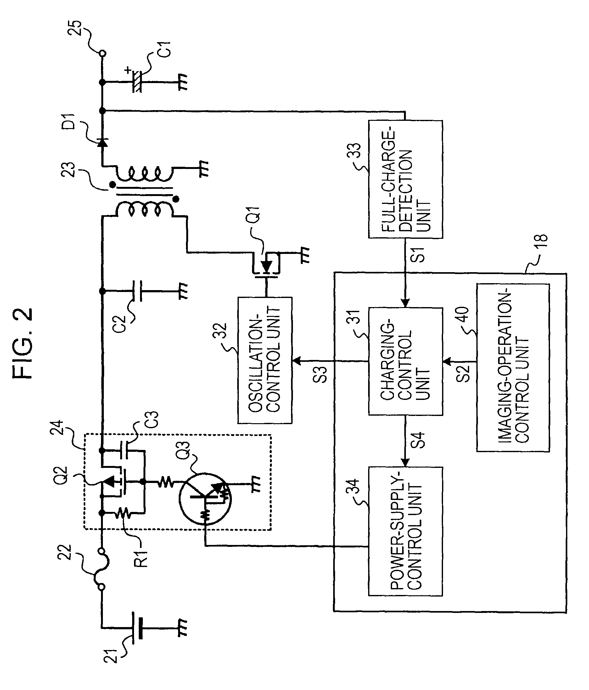
[0020]In the imaging apparatus according to the embodiment of the present invention, when the full-charge-detection unit does not detect the fully charged state of the main capacitor in the predetermined time after the power-supply-interrupting circuit has been set to be in the conducting state and the switching operation of the switching element has been started, the power-supply-interrupting circuit is set to be in the interrupting state. Thus, when an abnormality occurs in the switching element and a current continues flowing while the main capacitor is being charged, the interrupting state of the power-supply-interrupting circuit can prevent the current from flowing through the switching element, thereby preventing the switching element from generating heat. Therefore, the safety can be ensured.

Problems solved by technology

In this case, it is difficult to limit a supply of power from the direct-current power supply 51 to the step-up transformer 53.

Method used


Image

  • Imaging apparatus, strobe device, and charging-control method
  • Imaging apparatus, strobe device, and charging-control method
  • Imaging apparatus, strobe device, and charging-control method

Examples


Embodiment Construction

[0030]Embodiments of the present invention, in which imaging apparatuses capable of recoding captured images as digital data, such as digital still cameras, are provided as application examples, will be described in detail with reference to the accompanying drawings.

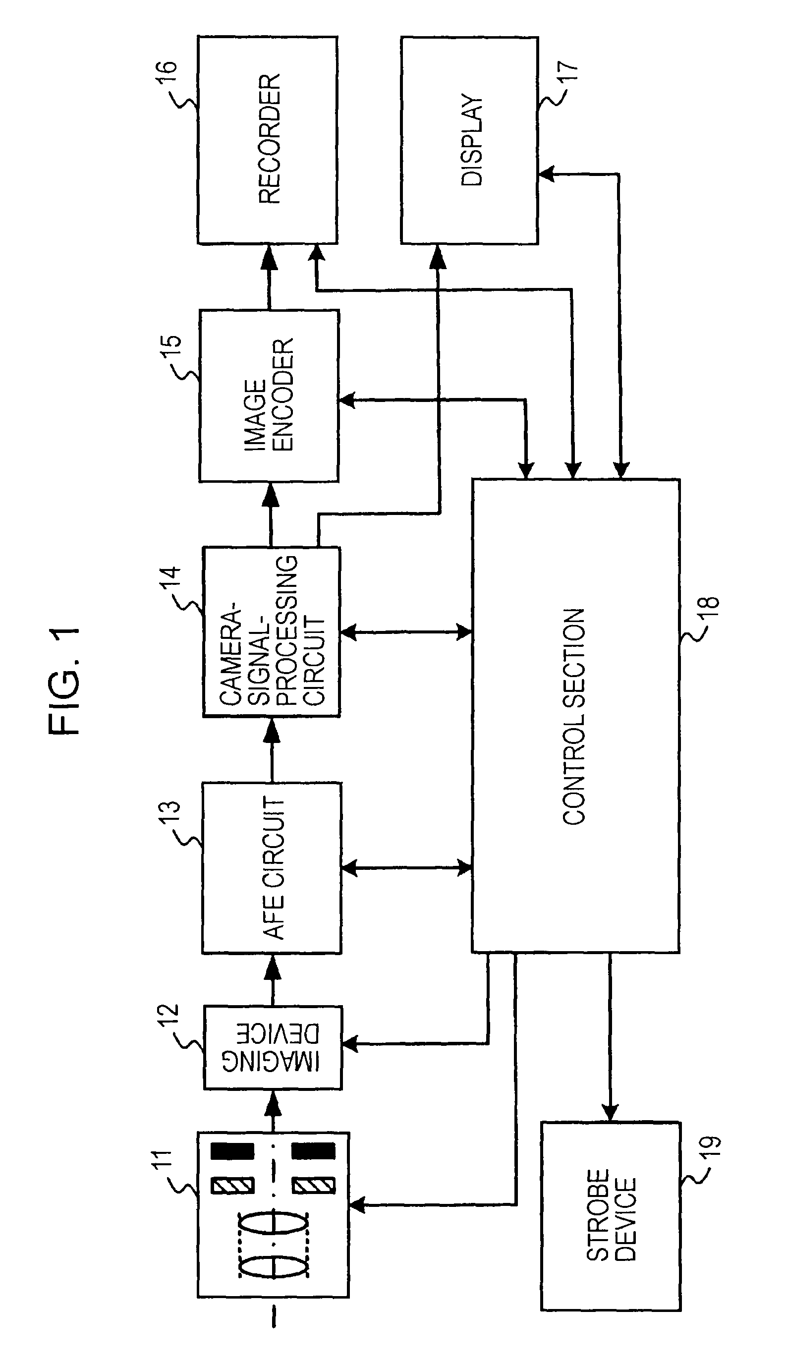
[0031]FIG. 1 is a block diagram of a configuration of a principal part of an imaging apparatus according to an embodiment of the present invention.

[0032]The imaging apparatus shown in FIG. 1 includes an optical block 11, an imaging device 12, an analog-front-end (AFE) circuit 13, a camera-signal-processing circuit 14, an image encoder 15, a recorder 16, a display 17, a control section 18, and a strobe device 19.

[0033]The optical block 11 includes a lens that gathers light from an object into the imaging device 12, a driving mechanism in which the lens is moved to adjust the focus of the lens and to perform a zooming operation, a shutter mechanism, and an iris mechanism. The lens, the driving mechanism, the shutter mechan...


PUM


Abstract

An imaging apparatus including a strobe device having a charging circuit of a separately excited oscillation type is provided. The apparatus includes a main capacitor in which charge is accumulated to supply power to a strobe-light-flashing unit, a step-up transformer including at least primary and secondary coils, a switching element that performs a switching operation to control a current supplied to the primary coil, a rectifier diode that rectifies a flyback pulse generated in the secondary coil to supply a charging voltage to the main capacitor, a power-supply-interrupting circuit that selectively interrupts power supplied from the power supply, a full-charge detection unit that detects whether the main capacitor reaches a fully charged state, and a power-supply-control unit that controls the power-supply-interrupting circuit so as to set the power-supply-interrupting circuit to be in an interrupting state.

Description

CROSS REFERENCES TO RELATED APPLICATIONS[0001]The present invention contains subject matter related to Japanese Patent Application JP 2007-102319 filed in the Japanese Patent Office on Apr. 10, 2007, the entire contents of which are incorporated herein by reference.BACKGROUND OF THE INVENTION[0002]1. Field of the Invention[0003]The present invention relates to an imaging apparatus including a strobe device, a strobe device, and a charging-control method for the strobe device. More particularly, the present invention relates to an imaging apparatus including a strobe device having a charging circuit of a separately excited oscillation type, a strobe device, and a charging-control method.[0004]2. Description of the Related Art[0005]In recent years, there have been various types of strobe-charging circuits used for strobe devices or the like. Charging circuits that have been used often lately are of a separately excited oscillation type, and more specifically, of a flyback transformer ...

Claims


Application Information

Patent Timeline
Patent Type & Authority Patents(United States)
IPC IPC(8): H05B37/00
CPCH05B41/32
Inventor TAKENAKA, TAKUYA
Owner SONY CORP
Learn More