Waterproof electrical connector

a technology of electrical connectors and water-proof connectors, which is applied in the direction of coupling device connections, cycle equipment, transportation and packaging, etc., can solve the problems of affecting the performance of electrical control components, and affecting the operation of electrically controlled components

Inactive Publication Date: 2003-05-06
SHIMANO INC
View PDF9 Cites 71 Cited by
  • Summary
  • Abstract
  • Description
  • Claims
  • Application Information

AI Technical Summary

Benefits of technology

Another object of the present invention is to provide an electrical connector with a releasable connection therebetween in case of the electrical cord is accidentally caught on an object during riding in order to avoid serious damage to the cord and prevent the rider from losing control over the bicycle.
Another object of the present invention is to provide a male electrical connector, which is relatively simple and inexpensive to manufacture and assemble.

Problems solved by technology

The electrical connections can often be contaminated so as to degrade performance of the operation of the electrically control component.
If the electrical connections get too dirty, the bicycle components and / or sensors may not operate properly.
Additionally, in certain riding conditions such as off-road type riding, the cyclist often encounters obstructions such as bushes or tree limbs.
Sometimes, these obstructions can catch the electrical wires or cords and affect performance of the electrical components and / or sensors.
Additionally, in some situations, other obstructions such as clothing, bicycle lock cables or tools can catch on the electrical wires or cords.
The problem with such non-releasable electrical connectors is that the electrical cord can get caught on an obstruction, which can result in the rider losing control over the bicycle and serious damage to the electrical cord.

Method used


Image

  • Waterproof electrical connector
  • Waterproof electrical connector
  • Waterproof electrical connector

Examples


third embodiment

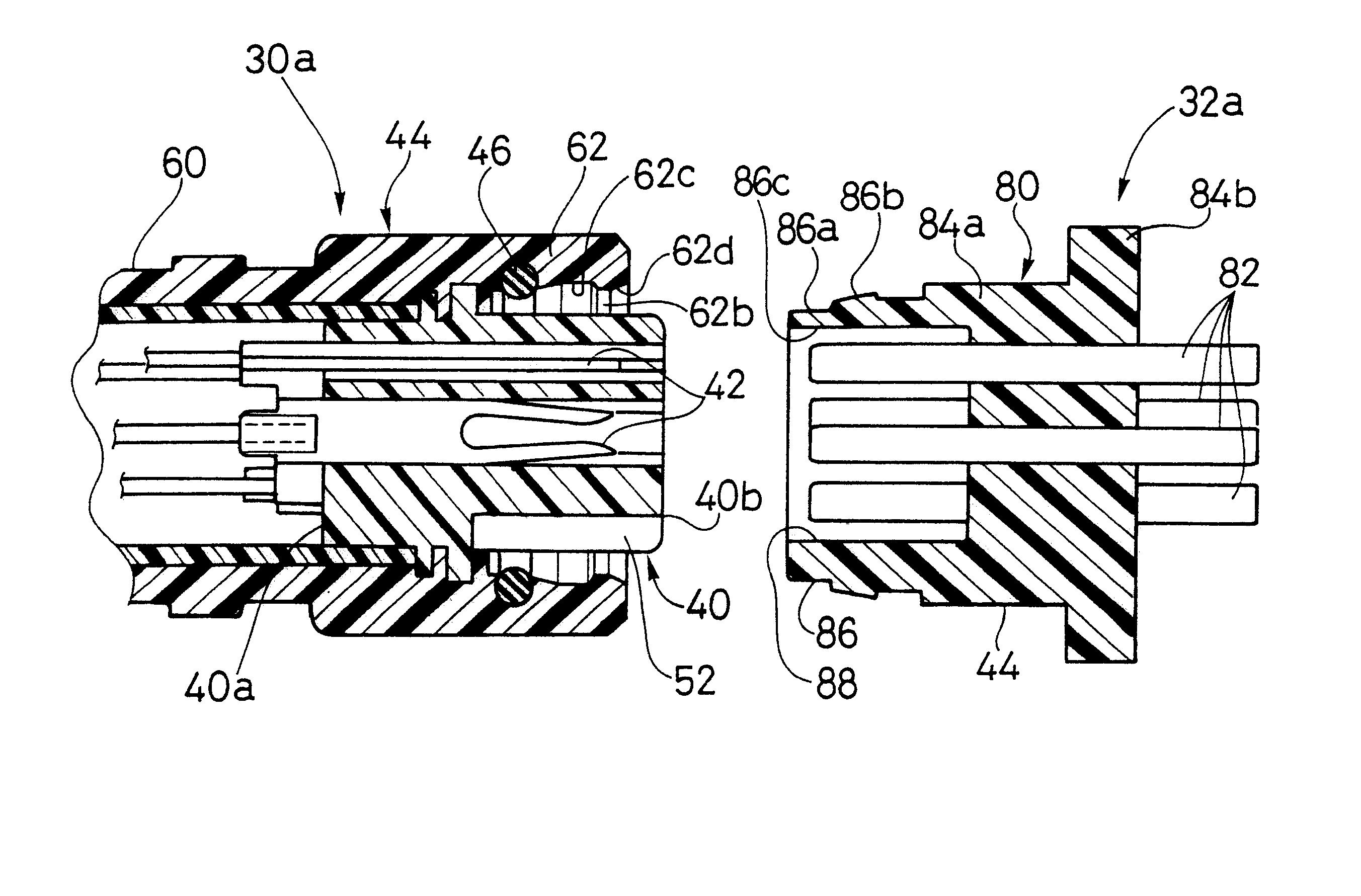
Referring now to FIG. 19, a female electrical connector 30a" is illustrated in accordance with a third embodiment of the present invention. In view of the similarity between the first and third embodiments, the parts of the third embodiment that are identical to the parts of the first embodiment will be given the same reference numerals as the parts of the first embodiment. Moreover, the descriptions of the parts of the third embodiment that are identical to the parts of the first embodiment may be omitted for the sake of brevity. The parts of the third embodiment that differ from the parts of the first embodiment will be indicated with a double prime (").

The female electrical connector 30a" basically has an electrical contact housing 40 with a plurality of first electrical contacts (not shown), an outer casing 44" molded on the electrical contact housing 40 and an annular sealing member 46" located between the electrical, contact housing 40 and the outer casing 44". Preferably, the...

fourth embodiment

Referring now to FIG. 20, a female electrical connector 30a'" is illustrated in accordance with a fourth embodiment of the present invention. In view of the similarity between the first and fourth embodiments, the parts of the fourth embodiment that are identical to the parts of the first embodiment will be given the same reference numerals as the parts of the first embodiment. Moreover, the descriptions of the parts of the fourth embodiment that are identical to the parts of the first embodiment may be omitted for the sake of brevity. The parts of the fourth embodiment that differ from the parts of the first embodiment will be indicated with a triple prime ('").

The female electrical connector 30a'" basically has an electrical contact housing 40 with a plurality of first electrical contacts (not shown) and an outer casing 44" molded on the electrical contact housing 40. The outer casing 44'" has an annular sealing member 46'" integrally formed therewith so as to be extend from the i...

fifth embodiment

This fifth embodiment is also similar to the fourth embodiment, except that the annular sealing member 46"" is constructed similar to the second embodiment such that the annular sealing member 46"" is compressed radially inwardly by the tubular portion 86 of the male electrical connector 32a during the coupling of the female and male electrical connectors 30a"" and 32a.

In this embodiment, the outer casing 44"" is constructed of two pieces. More specifically, the outer casing 44"" includes a rigid sleeve 45"" that overlies a resilient compressible member or inner part 62'". Preferably, the sleeve 45"" is constructed of a rigid, non-compressible material. For example, the sleeve 45"" can be constructed of metal or a very hard plastic material with relatively no flexibility or resiliency. In this embodiment, the annular sealing member 46"" is integrally formed with the compressible material of the inner part 62"" of the outer casing 44"". Preferably, the inner tubular part 62"" is form...


PUM


Abstract

Various electrically controlled devices of a bicycle are electrically coupled together by multi-conductor electrical cords. The ends of the electrical cords have an electrical connector that mates with a corresponding electrical connector provided in one of the electrically controlled devices. Each electrical connector of the electrical cords has an electrical contact housing with electrical contacts, an outer casing molded about the electrical contact housing, and an annular sealing member formed of a resilient and compressible material. The outer casing has an attachment portion fixed to one end of the electrical contact housing and a tubular portion radially spaced from the other end of the electrical contact housing. The annular sealing member is located in an annular space formed between the tubular portion and the electrical contact housing.

Description

1. Field of the InventionThis invention generally relates to an electrical connector. More specifically, the present invention relates an electrical connector.2. Background InformationBicycling is becoming an increasingly more popular form of recreation as well as a means of transportation. Moreover, bicycling has also become a very popular competitive sport for both amateurs and professionals. Whether the bicycle is used for recreation, transportation or competition, the bicycle industry is constantly improving the various components of the bicycle. Specifically, manufacturers of bicycle components have been continually improving performance, reliability and appearance of the various components.Recently, bicycles have been provided with an electronic drive train for smoother shifting. These electronic drive trains include a rear multi-stage sprocket assembly with a motorized rear derailleur and a front multi-stage sprocket assembly with a motorized front derailleur. These derailleu...

Claims


Application Information

Patent Timeline
Patent Type & Authority Patents(United States)
IPC IPC(8): H01R13/52H01R9/22B62J99/00H01R43/00H01R43/18
CPCH01R13/5221H01R9/223
Inventor NISHIMOTO, NAOHIRO
Owner SHIMANO INC
Why Eureka
Try Eureka