
Apparatus for electrophoresis

a technology of electrophoresis and apparatus, applied in the direction of electrolysis components, material analysis by electric/magnetic means, solid separation, etc., can solve the problems of improper placement in use, poor electrical contact, and expense of oil discarding

Inactive Publication Date: 2003-05-06
MACQUARIE RES
View PDF11 Cites 12 Cited by
  • Summary
  • Abstract
  • Description
  • Claims
  • Application Information

AI Technical Summary

Benefits of technology

In one preferred form, the tray is provided with the electrodes positioned in the troughs and having electrical terminals positioned at one end of the leads. When the tray is placed in the frame, the terminals connect to plugs positioned therein thus allowing the imposing of an electric potential between the leads.
A principal advantage of the present invention is that it allows the tray to be disposable although trays could be provided for multiple use, if desired. In the case of disposable trays containing electrodes any suitable conductive material compatible with electrophoresis could be used as the electrode although clearly cheaper electrodes such s graphite would be preferable to platinum if the tray is to be thrown away after use.
The apparatus according to the first aspect of the present invention also allows the possibility to stack a plurality of trays and carry out multiple separations simultaneously. The trays are removable for loading etc, and then would simply plug in to a suitable frame adapted to receive a number of trays stacked horizontally. Thus one power supply could be used for a number of trays.

Problems solved by technology

There are many difficulties and disadvantages with existing apparatus suitable for running immobilised pH gradients (IPGs).
All commercially available systems have electrodes which are removable and therefore can be placed incorrectly in use.
Many of the electrodes are resilient which can result in poor electrical contact.
This not only results in the expense of discarding the oil but also requires intense washing between runs and after each use.
Due the inherent design of current systems they have a relatively large footprint and thus require a large amount of bench space in use.
Another disadvantage of two-dimensional electrophoresis systems is that they are labor-intensive and time-consuming.
Elongate gels are awkward to handle and their use is prone to error and loss of samples and time.

Method used


Image

  • Apparatus for electrophoresis
  • Apparatus for electrophoresis
  • Apparatus for electrophoresis

Examples


Embodiment Construction

While the invention is susceptible to a wide range of configurations, procedures, and embodiments, it will best be understood by a detailed examination of one specific structure and its mode of operation. Such a structure is shown in the drawings, and its construction and use are explained below.

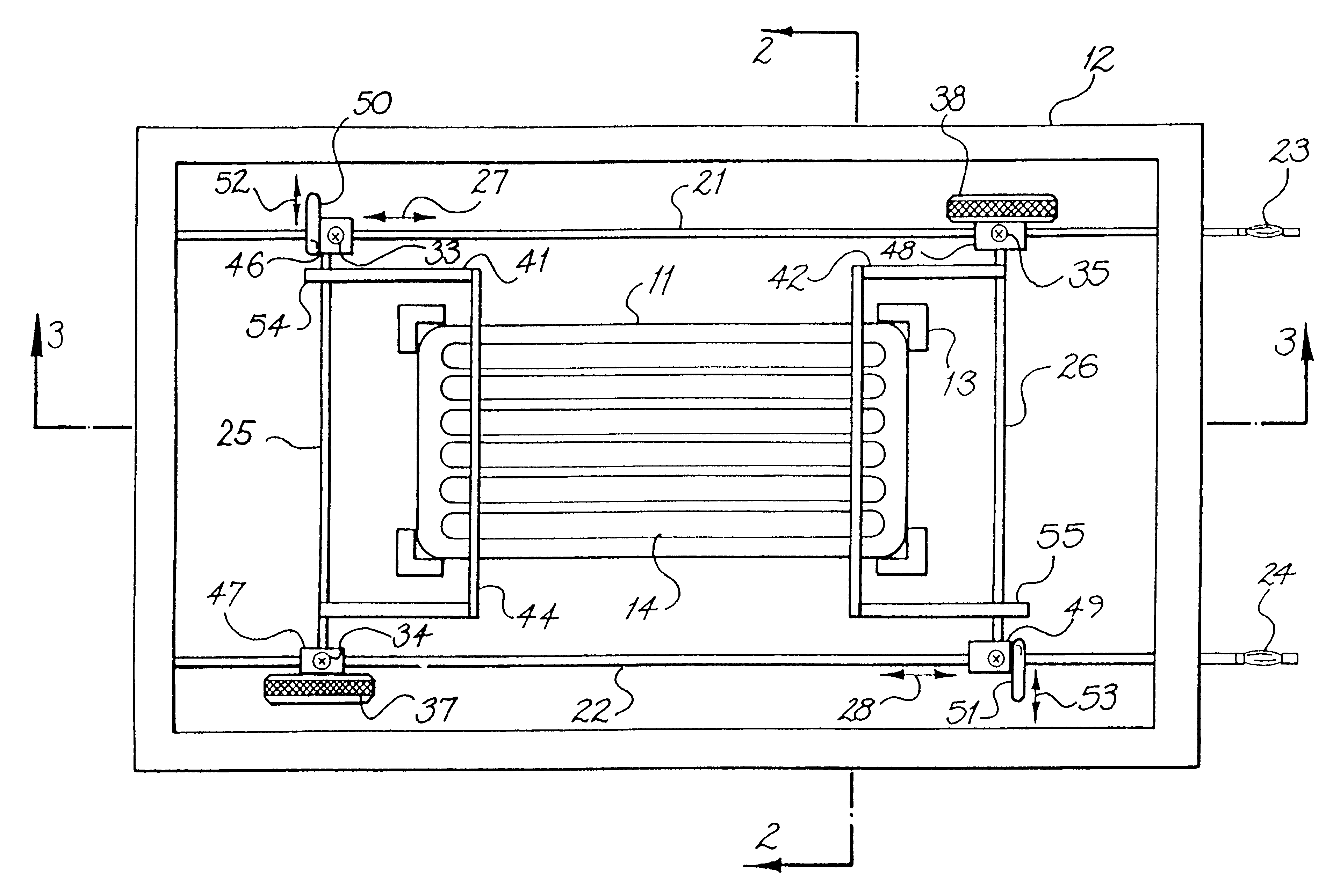
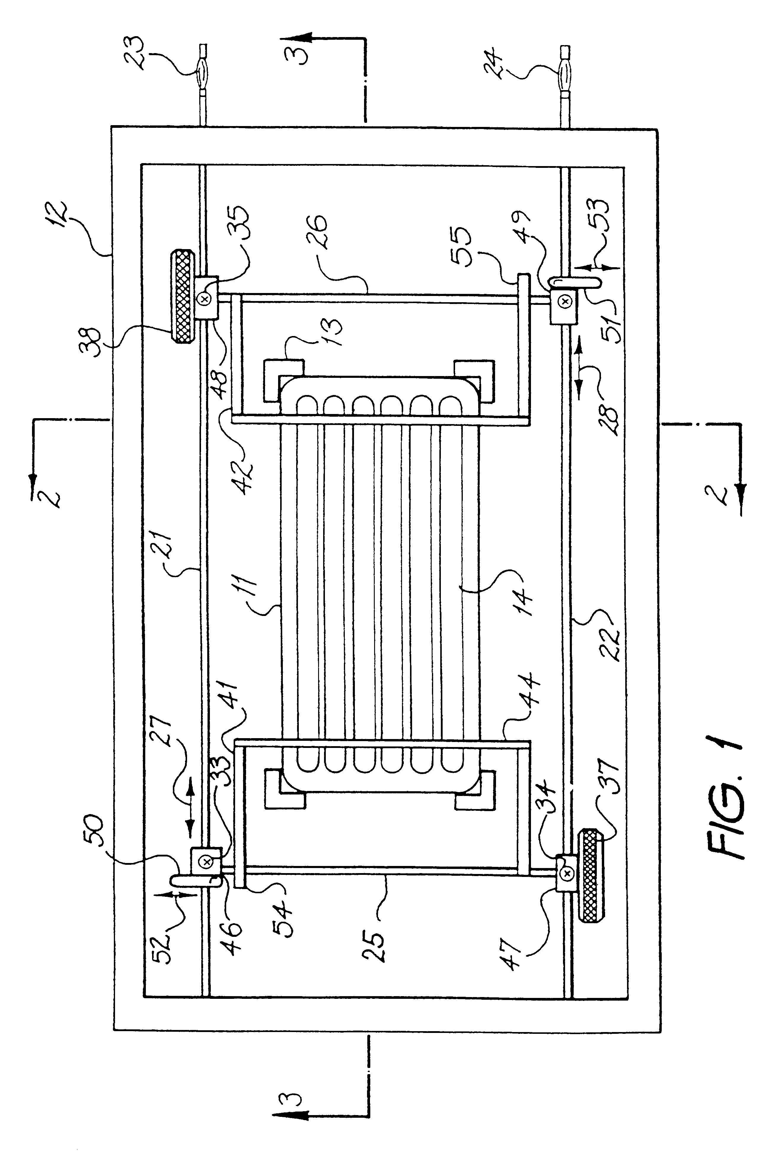
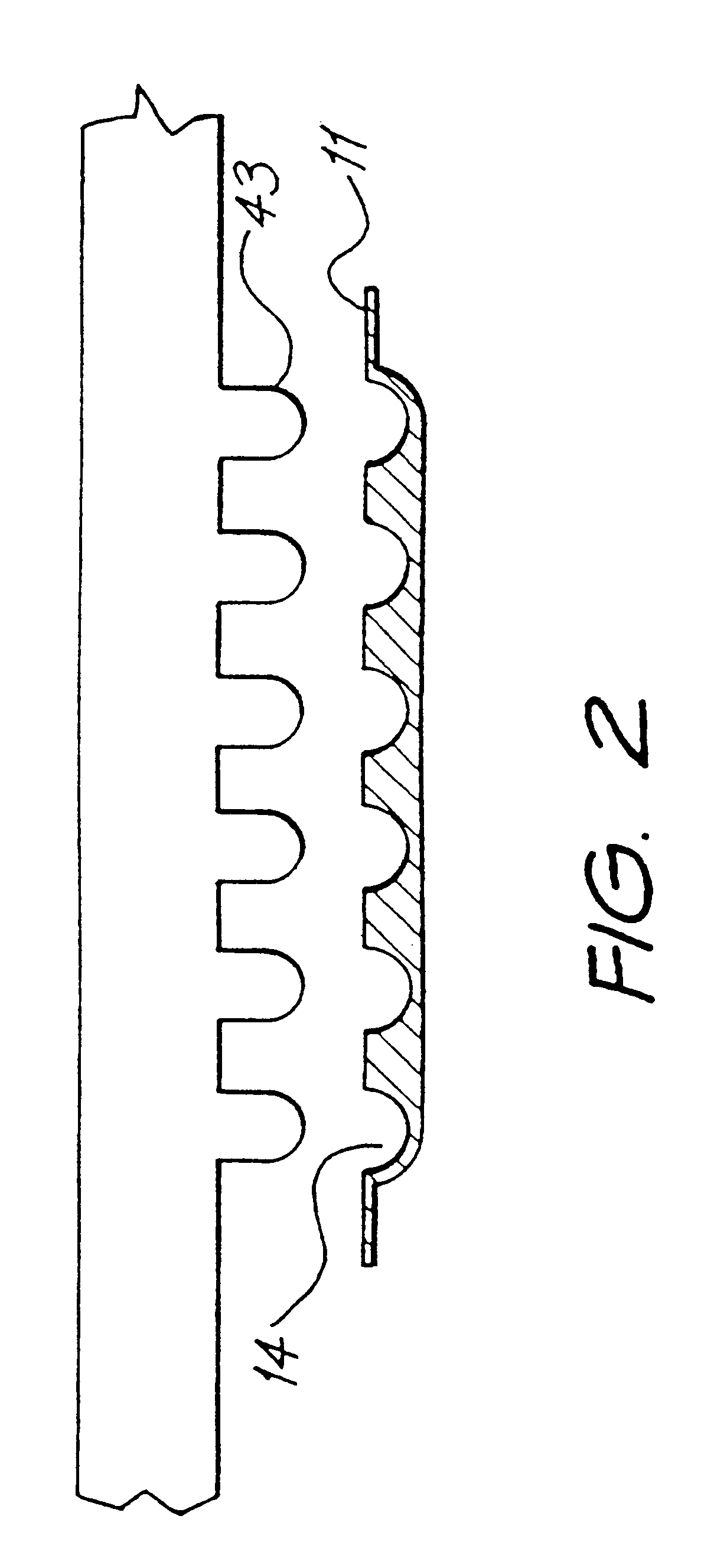
In the top plan view of FIG. 1, the tray 11 is shown, held inside a frame 12 by retaining blocks 13. The tray is shown in transverse cross section in FIG. 2, and contains an array of parallel troughs 14, which are visible from above in FIG. 1 and in profile in FIG. 2. Each trough extends almost the entire length of the tray 11, and is long enough to contain a single rod- or strip-shaped gel that will be used as the first dimension separation in two-dimensional electrophoresis. The length is otherwise not critical and can vary to accommodate gel strips or rods of various sizes. An appropriate length for most applications of this invention will generally range from about 6 cm to about 20 cm. T...


PUM

PropertyMeasurementUnit
lengthaaaaaaaaaa
lengthaaaaaaaaaa
electric potentialaaaaaaaaaa

Abstract

An electrophoresis apparatus for the simultaneous electrophoretic separation of a plurality of component mixtures using a disposable tray having a plurality of parallel troughs shaped to retain an elongate strip of isoelectric focusing medium and sufficient liquid to immerse the elongate strip. A frame is provided to retain the tray in a horizontal position using a pair of rotatably mounted support members moving between an open and closed position. Support members are also connected to a plurality of electrodes aligned with each of the troughs so that the electrodes are positioned clear of the troughs in the open position and positioned in the troughs when in the closed position.

Description

The invention relates to apparatus for the separation of macromolecules by electrophoresis, particularly by isoelectric focusing.Two-dimensional (2D) electrophoresis is a useful and well-known separation technique for purifying macromolecules and separating complex macromolecule mixtures, often providing a much higher resolving power than typical electrophoretic separation in one dimension or direction.In two-dimensional electrophoresis, separation is performed under two different conditions or according to two different separation parameters, one in a first direction and the other in a second direction which is usually perpendicular to the first. The first dimension of the separation is typically performed in an elongate rod-shaped or strip-shaped gel with migration and separation of macromolecules occurring along the length of the gel. Once the macromolecules have been grouped into individual zones along the length of the gel, the gel is placed along one edge of a slab gel and the...

Claims


Application Information

Patent Timeline
Patent Type & Authority Patents(United States)
IPC IPC(8): B01D57/02G01N27/447B03C5/00C08F2/58
CPCB01D57/02G01N27/44782G01N27/44704
Inventor WILLIAMS, KEITH LESLIEMOLLOY, MARKGOOLEY, ANDREW ARTHURPACKER, NICOLLE HANNAHHERBERT, BENWALSH, BRADLEYFERNWOOD, GEORGEGARFIN, DAVID
Owner MACQUARIE RES
Learn More