Linear oscillating actuator

a technology of linear oscillating actuator and actuator, which is applied in the direction of dynamo-electric components, dynamo-electric machines, magnetic circuit shapes/forms/constructions, etc., can solve the problem that the actuator suffers from undesired vibration around the mass of the actuator

Inactive Publication Date: 2003-05-06
MATSUSHITA ELECTRIC WORKS LTD
View PDF4 Cites 131 Cited by
  • Summary
  • Abstract
  • Description
  • Claims
  • Application Information

AI Technical Summary

Problems solved by technology

Due to this offset arrangement of the individual oscillating systems from the mass center of the actuator, the actuator suffers from undesired vibrations around its mass center

Method used


Image

  • Linear oscillating actuator
  • Linear oscillating actuator
  • Linear oscillating actuator

Examples


Embodiment Construction

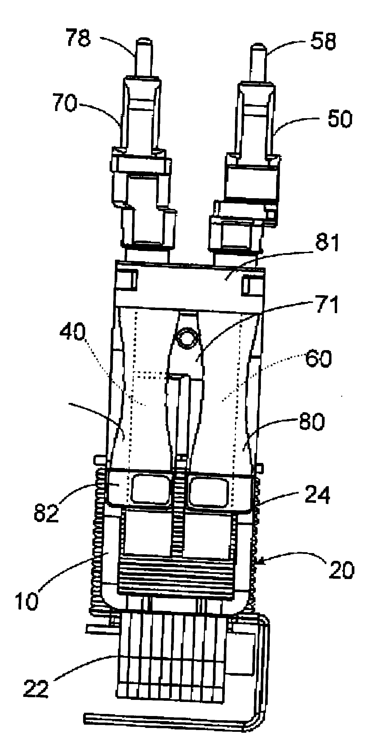
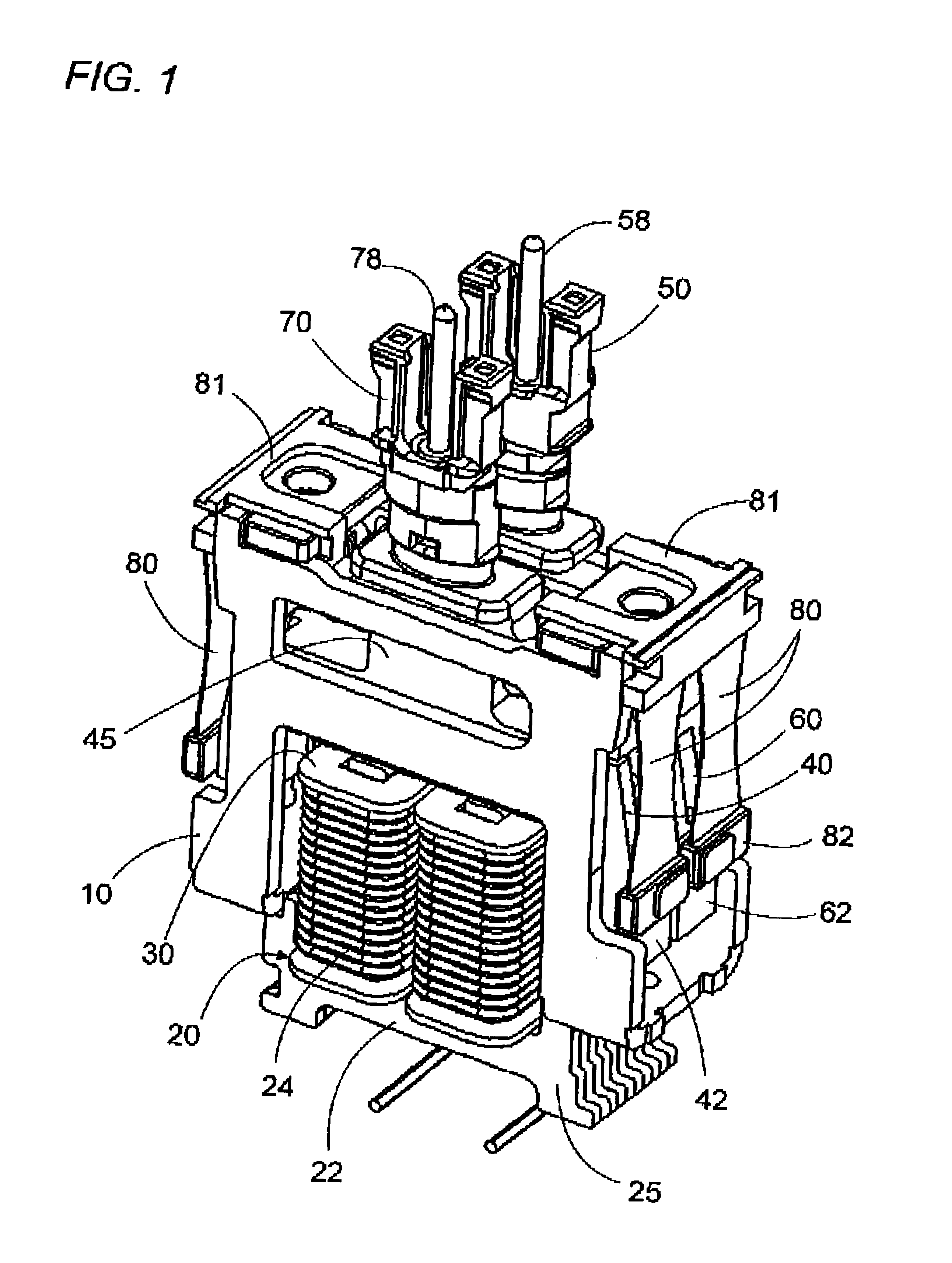
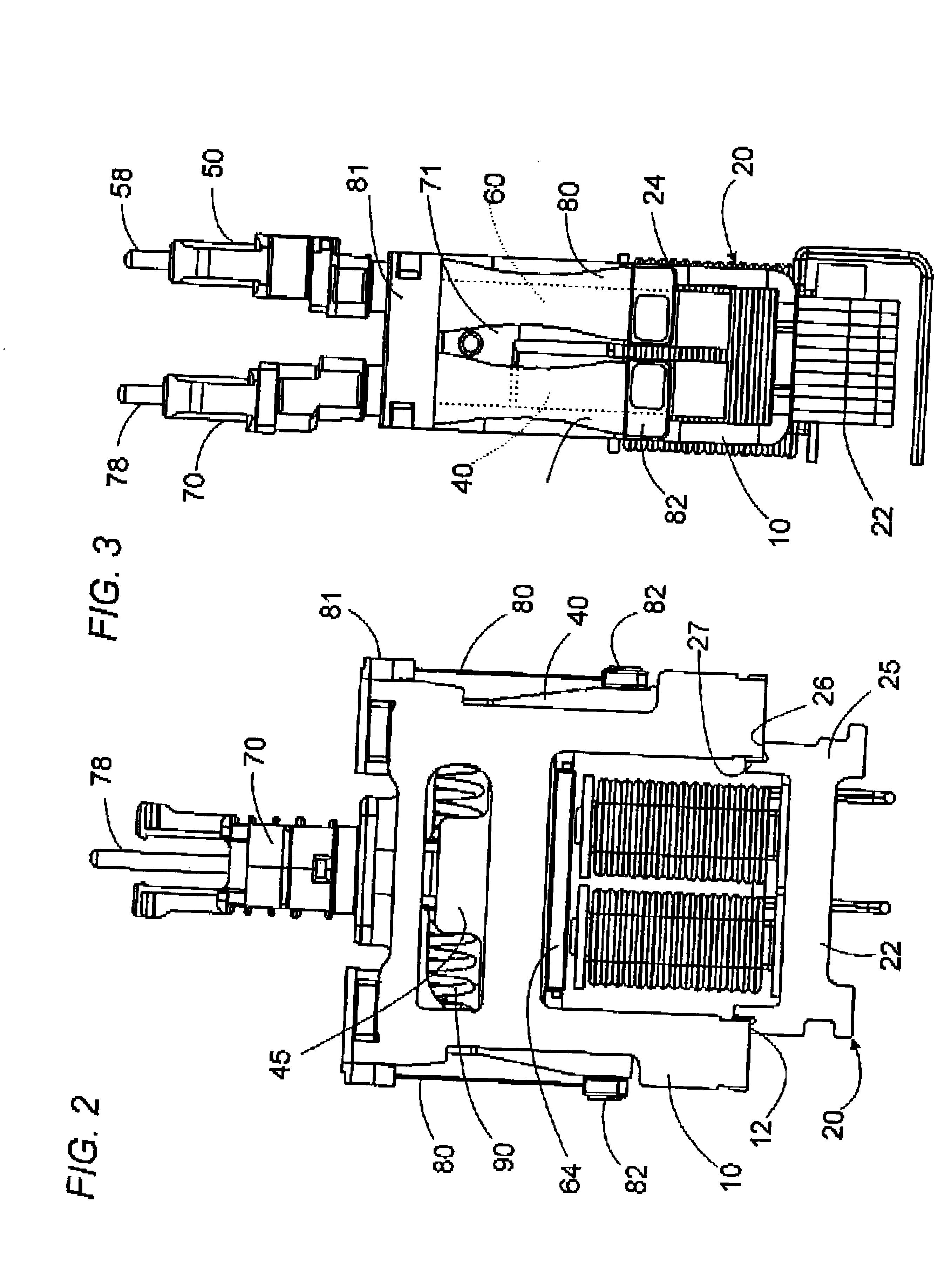
Now referring to FIGS. 1 to 4, there is shown a linear oscillating actuator in accordance with the present invention which is adapted to be incorporated in a dry shaver as a driving source for oscillating a pair of inner cutters respectively in parallel linear paths relative to an outer cutter. The actuator is basically composed of a chassis 10 mounting a stator 20 and a pair of oscillators, i.e., a first oscillator 40 and a second oscillator 60. The stator 20 is realized in the form of an electromagnet composed of a core 22 and a pair of windings 24 disposed respectively around two upright poles 23 of the core 22. The windings 24 are connected in series and supplied with an alternating current to generating a magnetic field of alternating polarity. The first and second oscillators 40 and 60 are suspended from the chassis 10 respectively by means of leaf springs 80 so as to be movable only in the linear paths defined along a horizontal length of the chassis 10. In this connection, t...


PUM


Abstract

An improved linear oscillating actuator is capable of minimizing the undesired vibrations while moving first and second oscillators in parallel paths. The first and second oscillators carry first and second drive elements respectively for driving connection to individual reciprocating loads. The first and second drive elements project upwardly respectively from the first and second oscillators such that the first drive element is disposed immediately upwardly of the second oscillator and the second drive elements is disposed immediately upwardly of the first oscillator. With this reverse arrangement of the first and second drive elements relative to the first and second oscillators, the individual oscillating systems each including the oscillator, the drive element and the corresponding reciprocating load can have its mass center disposed in close proximity to a mass center of the actuator, thereby enabling to reduce undesired vibrations which would otherwise occur around the mass center of the actuator.

Description

1. Field of the InventionThe present invention is directed to a linear oscillating actuator, and more particularly to a linear oscillating actuator having a pair of oscillators moving in parallel paths for driving individual loads.2. Description of the Prior ArtA linear oscillating actuator has been utilized in many fields as an alternative to the rotary driving source. Particularly, as disclosed in U.S. Pat. No. 5,632,087, the linear actuator has found itself advantageous for use as a driving source of dry shavers of reciprocatory type. When applied to the shaver having a pair of inner cutters, i.e., the reciprocating loads, the linear oscillating actuator is designed to have a corresponding pair of oscillators running in parallel oscillating paths and being adapted for driving connection respectively with the inner cutters. In this instance, each individual oscillating system composed of the oscillator and the corresponding reciprocating load has its mass center offset in a latera...

Claims


Application Information

Patent Timeline
Patent Type & Authority Patents(United States)
IPC IPC(8): H02K33/00H02K33/10
CPCH02K33/10B26B19/288B26B19/282
Inventor SHIMIZU, HIROAKIMOTOHASHI, RYOYABUUCHI, HIDEKAZUNISHINAKA, TAKAHIROKOBAYASHI, NOBORU
Owner MATSUSHITA ELECTRIC WORKS LTD
Why Eureka
Try Eureka