MOS transistors substitute circuit having a transformer/data interface function, particularly for ISDN networks and corresponding control and driving switch configuration

a transistor and data interface technology, applied in the direction of time-division multiplexing selection, transmission, energy consumption reduction, etc., can solve the problems of power availability and production cos

Inactive Publication Date: 2003-05-06
STMICROELECTRONICS SRL
View PDF8 Cites 34 Cited by
  • Summary
  • Abstract
  • Description
  • Claims
  • Application Information

AI Technical Summary

Problems solved by technology

Minimizing energy dissipation is highly important under RM emergency conditions; in such circumstances, in fact, no mains supply would be available, and the available power would be limited to the small power that the DC/DC converter at the interface circuits of the reference po

Method used


Image

  • MOS transistors substitute circuit having a transformer/data interface function, particularly for ISDN networks and corresponding control and driving switch configuration
  • MOS transistors substitute circuit having a transformer/data interface function, particularly for ISDN networks and corresponding control and driving switch configuration
  • MOS transistors substitute circuit having a transformer/data interface function, particularly for ISDN networks and corresponding control and driving switch configuration

Examples


Embodiment Construction

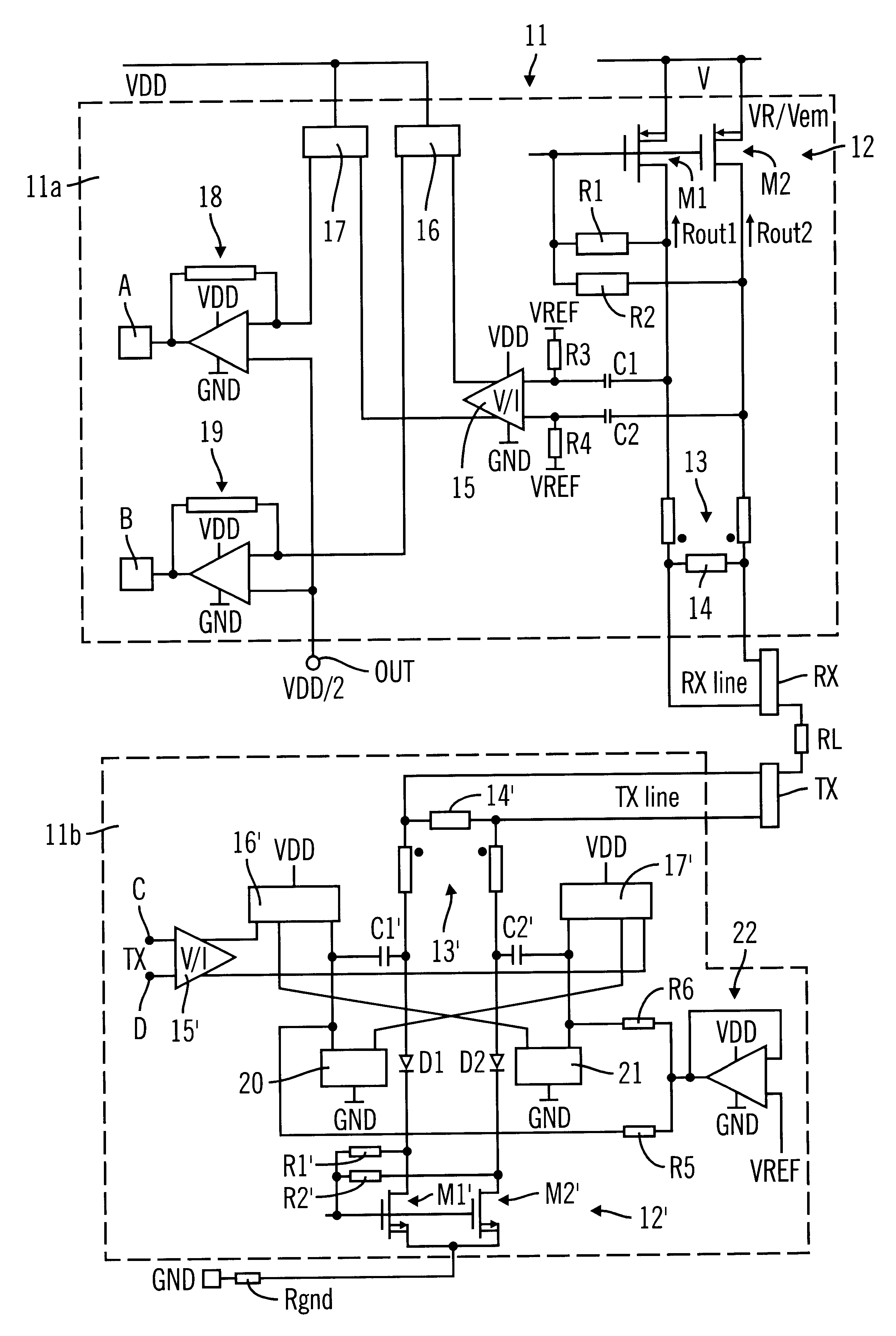
The embodiment relates to a MOS transistors substitutive circuit having a transformer / data interface function, particularly for ISDN networks, which circuit comprises first and second power supply / transmitter blocks, said first power supply / transmitter block being connected between a voltage reference and a first data interface, and said second power supply / transmitter block being connected between a ground potential reference and a second data interface, said first and second power supply / transmitter blocks being further connected to a supply voltage reference.

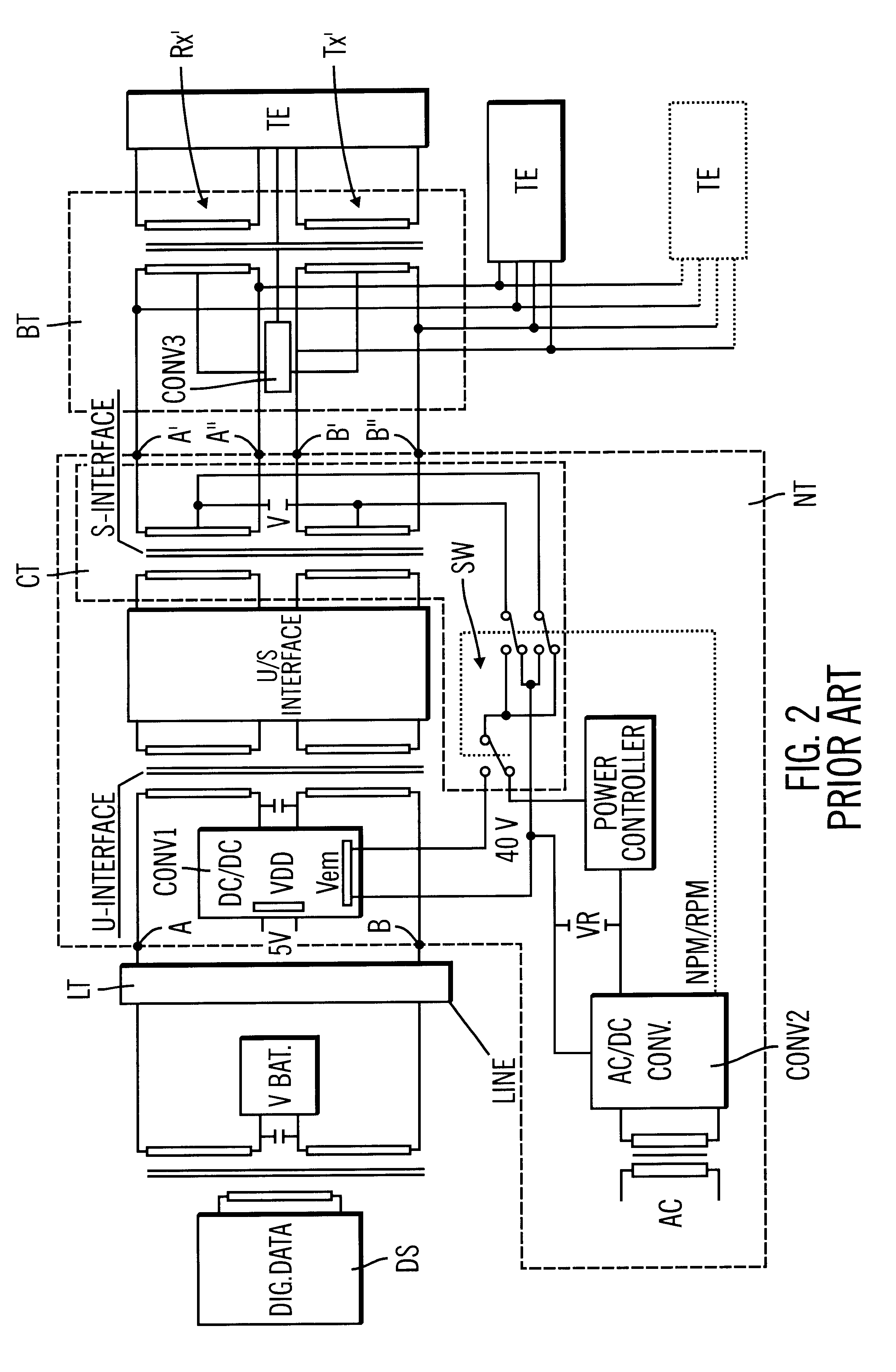
The embodiment also relates to a control and driving switch configuration for substitutive transformer / data transmitter circuits in a network termination, in particular ISDN network terminations, said network termination including first and second converters connected to a ground potential reference, said first converter delivering a supply voltage and an emergency voltage and said second converter delivering a remote supply ...


PUM


Abstract

The invention relates to a MOS transistors substitutive circuit having a transformer/data interface function, in particular for ISDN networks, comprising first (11a) and second (11b) power supply/transmitter blocks, the first power supply/transmitter block (11a) being connected between a voltage reference (V) and a first data interface (RX), and the second power supply/transmitter block (11b) being connected between a ground potential reference (GND) and a second data interface (TX), both power supply/transmitter blocks being connected to a supply voltage reference (VDD). The MOS transistors substitutive circuit according to the invention comprises first (12) and second (12') MOS transistor pairs connected to the voltage reference (V), the MOS transistors being diode configured and held in their saturation range, so as to have a high A.C. impedance and virtually zero D.C. impedance, thereby minimizing power dissipation through the substitutive circuit.The invention also concerns a control and driving switch configuration for a network termination of at least first (11) and second (11') MOS transistors substitutive circuits according to the invention, operating respectively in a first condition ("normal condition") of operation of the network termination characterized by the presence of the polarity reverse control signal (Scrp), and a second condition ("RM emergency condition") of operation of the network termination characterized by the absence of the polarity reverse control signal (Scrp). The control configuration selects the voltage reference being applied to the power supply/transmitter blocks.

Description

This application is based upon and claims priority from prior European Patent Application No. 97-830462.4, filed Sep. 23, 1997, the entire disclosure of which is herein incorporated by reference.1. Field of the InventionThis invention relates to a MOS transistors substitutive circuit having a transformer / data interface function, particularly for ISDN networks, and corresponding control and driving switch configuration.The invention particularly, but not exclusively, concerns an ISDN network termination, and the description that follows will make reference to that application for simplicity of illustration.2. Description of the Related ArtAs is well known, technological advancements in the telephone field have made it necessary to provide telephone terminal units with additional functions.An important additional function is, besides voice transmission, the transmission of information relating to new products and / or services, such as facsimile operations, video communications, network...

Claims


Application Information

Patent Timeline
IPC IPC(8): H04L12/00H04M19/08H04Q11/04
CPCH04L12/00H04M19/08H04Q11/0435H04Q2213/13003H04Q2213/1308H04Q2213/13082H04Q2213/13322H04Q2213/13166H04Q2213/13202H04Q2213/13209H04Q2213/13305H04Q2213/1332H04Q2213/1309Y02D30/70
Inventor CONSIGLIO, PIETROLARI, FERDINANDOANTONINI, CARLO
Owner STMICROELECTRONICS SRL
Why Eureka
Try Eureka