Incremental forming method and apparatus for the same

a technology of forming method and flange, which is applied in the direction of manufacturing tools, metal-working feeding devices, shaping tools, etc., can solve the problems of difficult to form a flange having a high height, high price, and difficult to carry out overlapping welding

Inactive Publication Date: 2003-05-13
HITACHI LTD
View PDF6 Cites 57 Cited by
  • Summary
  • Abstract
  • Description
  • Claims
  • Application Information

AI Technical Summary

Benefits of technology

An object of the present invention is to provide an incremental forming method for easily forming a plate in a predetermined shape.

Problems solved by technology

Since the female die and the male die are required, the price becomes high.
For example, when a cylinder is overlapped and joined to the flange, when the flange is not formed in a rectangular shape, it hard to carry out overlapping welding.
Further, it is difficult to form a flange having a high height.

Method used


Image

  • Incremental forming method and apparatus for the same
  • Incremental forming method and apparatus for the same
  • Incremental forming method and apparatus for the same

Examples


first embodiment

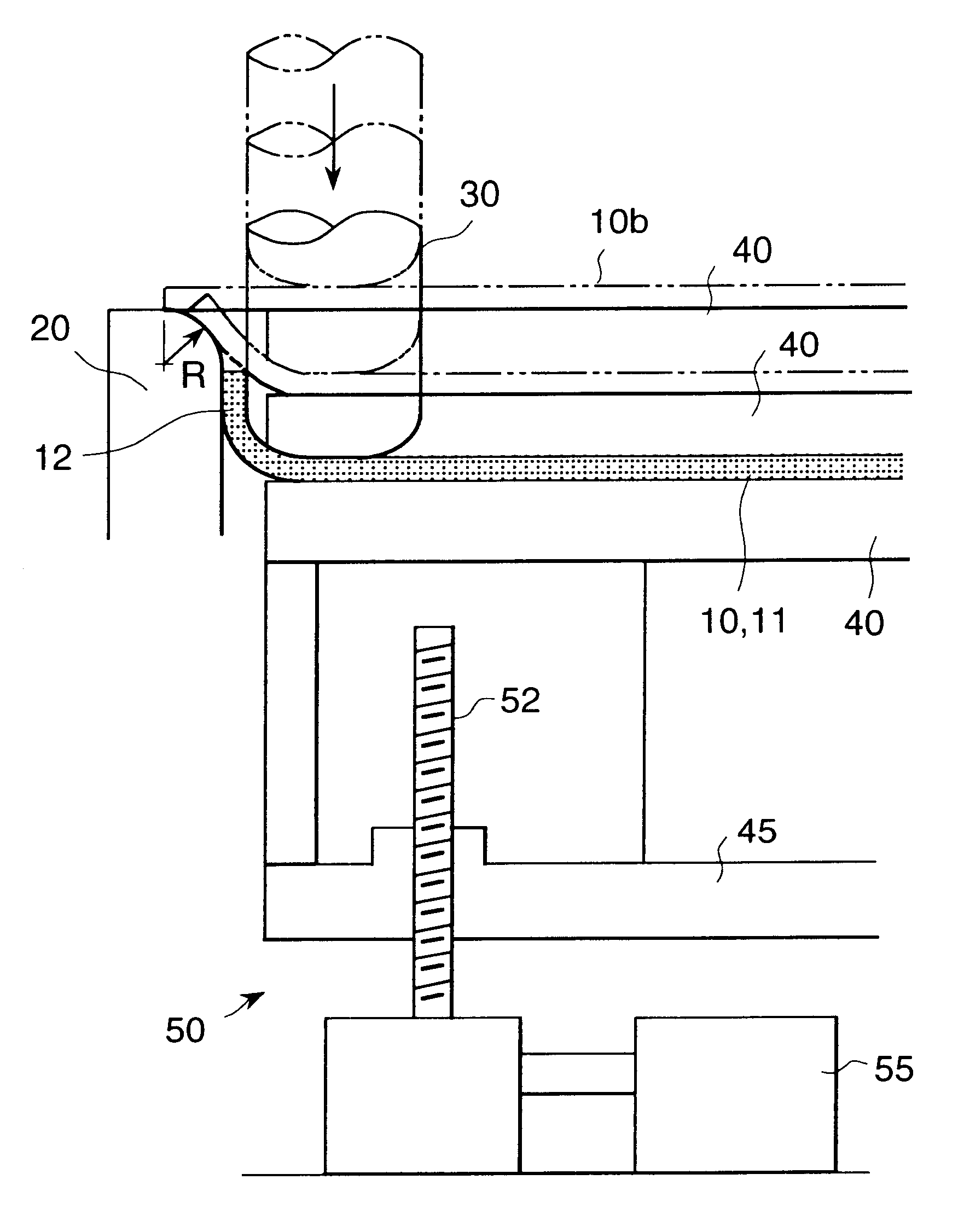
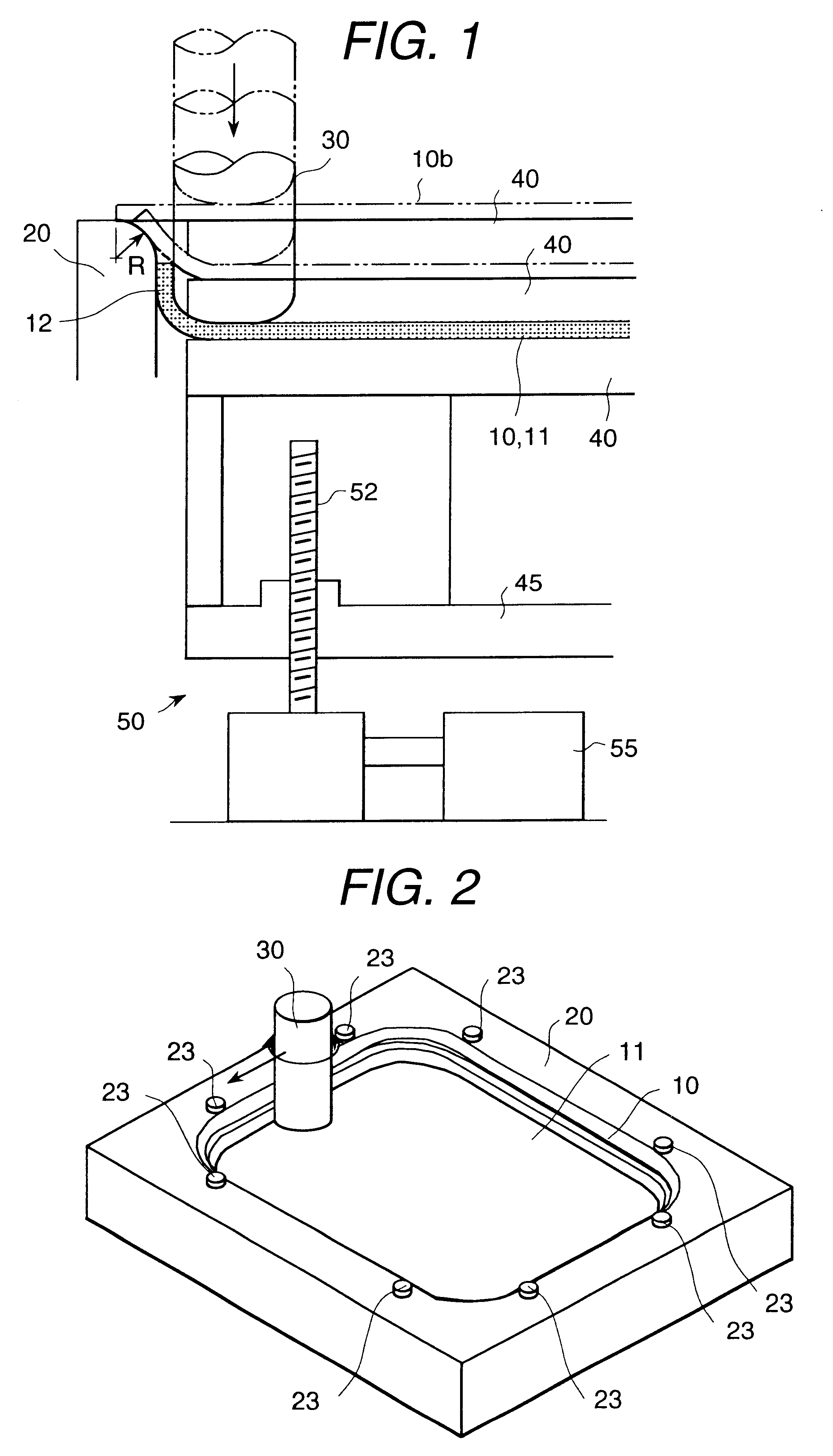
an incremental forming method and an apparatus for carrying out the method according to the present invention will be explained with reference to FIG. 1 to FIG. 5. FIG. 1 shows substantially only the left end portion of the apparatus, and it should be understood that this apparatus is symmetrical on right and left sides. FIG. 2 shows a condition during forming of a molded product.

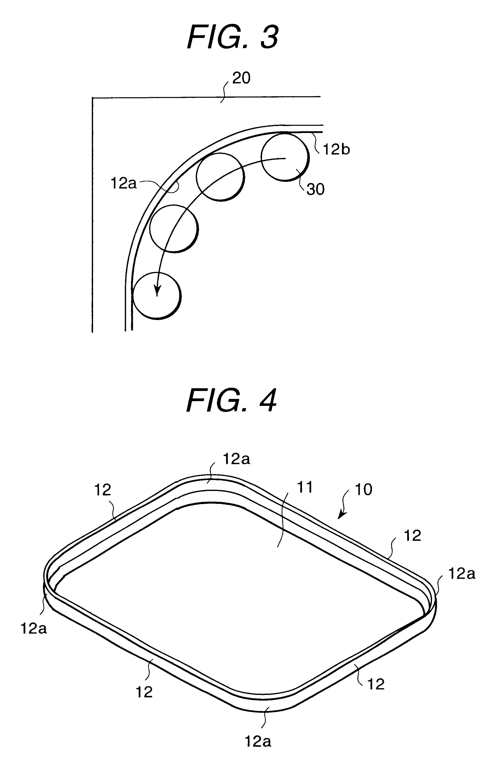
As seen in FIG. 4, a molded product 10 has a bottom 11, and a flange 12 is provided on an outer peripheral portion thereof. The molded product 10 is composed of four sides, and each side is linear, while a corner portion 12a where two adjacent sides are joined has a circular arc shape. The face of the bottom 11 and the face of the flange 12 are almost perpendicular to each other. The molded product 10 can be used by itself, and, in addition to this, it can be used as a cover forming an end portion of a cylindrical member. When the flange 10 and the end portion of the cylindrical member are overlapped and fi...


PUM

PropertyMeasurementUnit
diameteraaaaaaaaaa
thicknessaaaaaaaaaa
heightaaaaaaaaaa

Abstract

In a state in which a material (blank) cut in a predetermined shape is mounted on a die and the bottom of the material is supported by a seat, the material is pressed by a tool from above and the tool is moved along the die so that the material is incrementally formed. The bottom of the material is fixed, so that the material is not inclined and can be formed in a predetermined shape. A circular arc portion of a flange is processed in a state in which it is clamped by the female die and the tool, so that the circular arc portion of the flange is not spread outside and the perpendicularity between the flange of the circular arc portion and the bottom can be increased.

Description

BACKGROUND OF INVENTIONThe present invention relates to an incremental forming method for gradually processing a plate; and, more particularly, the invention relates to an incremental forming method for producing a molded product having a flange in an end portion of a plate.Conventionally, a molded product having a flange at an end portion of a plate is manufactured by inserting and pressing the plate between a female die and a male die. Since the female die and the male die are required, the price becomes high.As a means for reducing the number of dies, an incremental forming method has proposed, as shown in FIGS. 18 to 20 in Japanese patent application laid-open publication Hei 11-310371. In this method, an outer periphery of a piece of material is fixed to a female die, the material is pressed with a rod-shaped tool, the rod-shaped tool is moved along an inner peripheral face of the female die, and a sponson processing is incrementally carried out on the plate. On the other hand,...

Claims


Application Information

Patent Timeline
Patent Type & Authority Patents(United States)
IPC IPC(8): B21D22/00B21D22/14B21D22/18
CPCB21D22/14B21D37/04B21D43/026B21D43/04B21D43/18B21D43/20
Inventor OKADA, NORIHISAKAWAMURA, WATARU
Owner HITACHI LTD
Why Eureka
Try Eureka