
Lubricating system for OHC engine

a technology of lubricating system and overhead camshaft, which is applied in the direction of drip or splash lubrication, machine/engine, auxillary lubrication, etc., can solve the problems of increasing the number of components, raising the oil temperature, and large stirring resistance to become a rotational load

Inactive Publication Date: 2003-05-13
SUBARU CORP
View PDF15 Cites 13 Cited by
  • Summary
  • Abstract
  • Description
  • Claims
  • Application Information

AI Technical Summary

Benefits of technology

An object of the present invention is to securely supply a lubricating oil to a timing system without increasing the number of components in an OHC general-purpose engine.
According to the present invention, droplets of the oil can be splashed in the three-dimensional inclined direction, i.e., to the side direction of the scraper. Therefore, the droplets of the oil can be supplied to the timing system offsetted to the scraper in a longitudinal direction of the crankshaft. Thus, the timing system of the OHC engine can be securely lubricated without increasing the number of the components even though being offsetted from the scraper,

Problems solved by technology

However, there was a problem of resulting in a cost up by increasing the number of components and in a complicated structure in the case of the lubricating system as described in the Publication No. Hei. 8-177441 since the oil dipper is disposed on an axis different from that of a crankshaft.
In addition, there was also a problem of causing not only a large stirring resistance to become a rotational load, but also a raised oil temperature since the water mill wheel dips the lubricating oil up from the oil pan.
Furthermore, there was a disadvantage that the height of the engine is increased by the height of the oil dipper.
In addition, this system can cause less stirring resistance, resulting in less raised oil temperature, since the paddle type of dipper moves as cutting the oil.
Although, however, such a dipper can splash the oil along the circumference direction of the connecting rod, the dipper can not splash it toward a side of the connecting rod.
Therefore, the valve-operating system of OHC engine can not be well lubricated by such a dipper since the valve-operating system deviates from the connecting rod in the longitudinal direction of the crankshaft.

Method used


Image

  • Lubricating system for OHC engine
  • Lubricating system for OHC engine
  • Lubricating system for OHC engine

Examples


Embodiment Construction

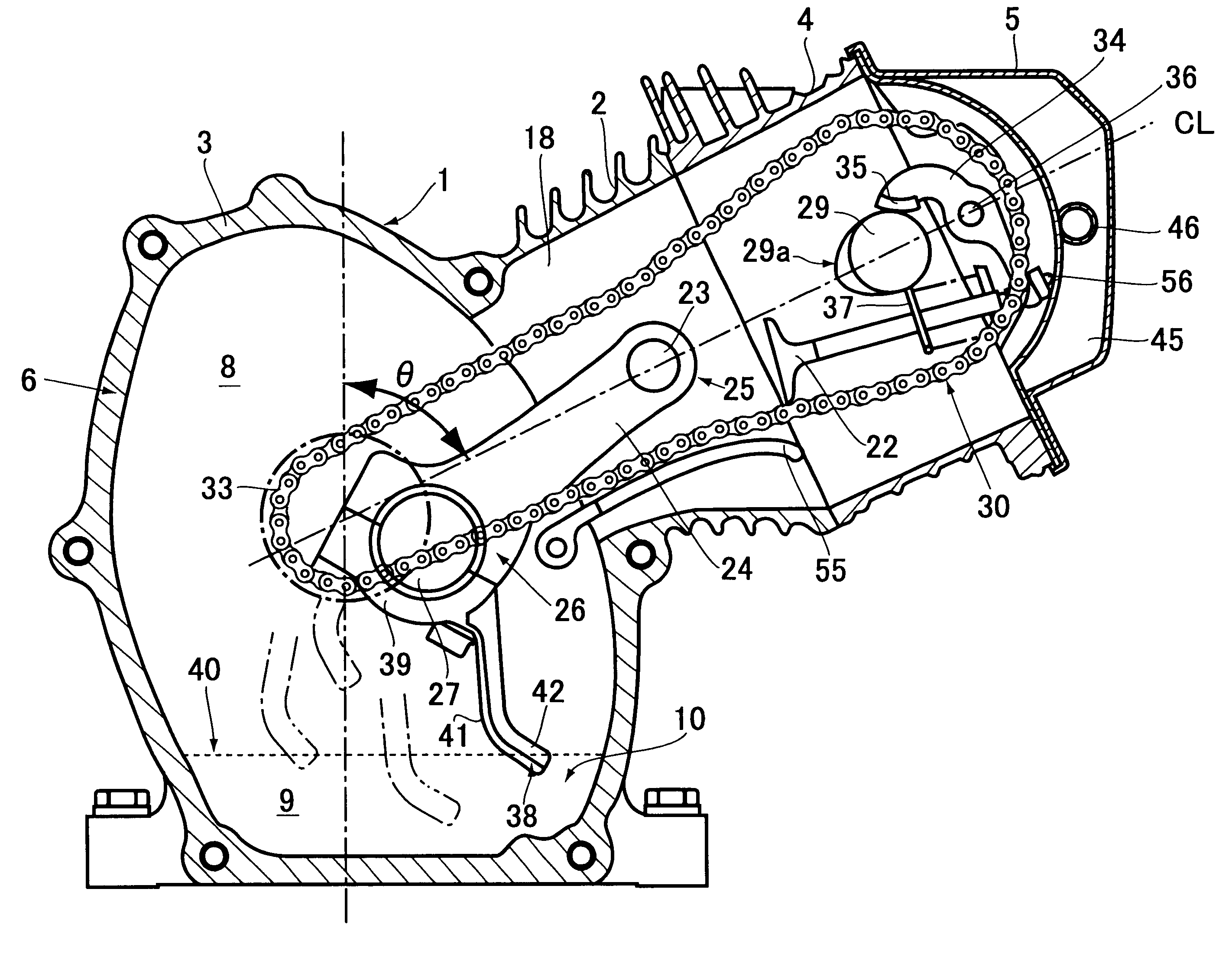
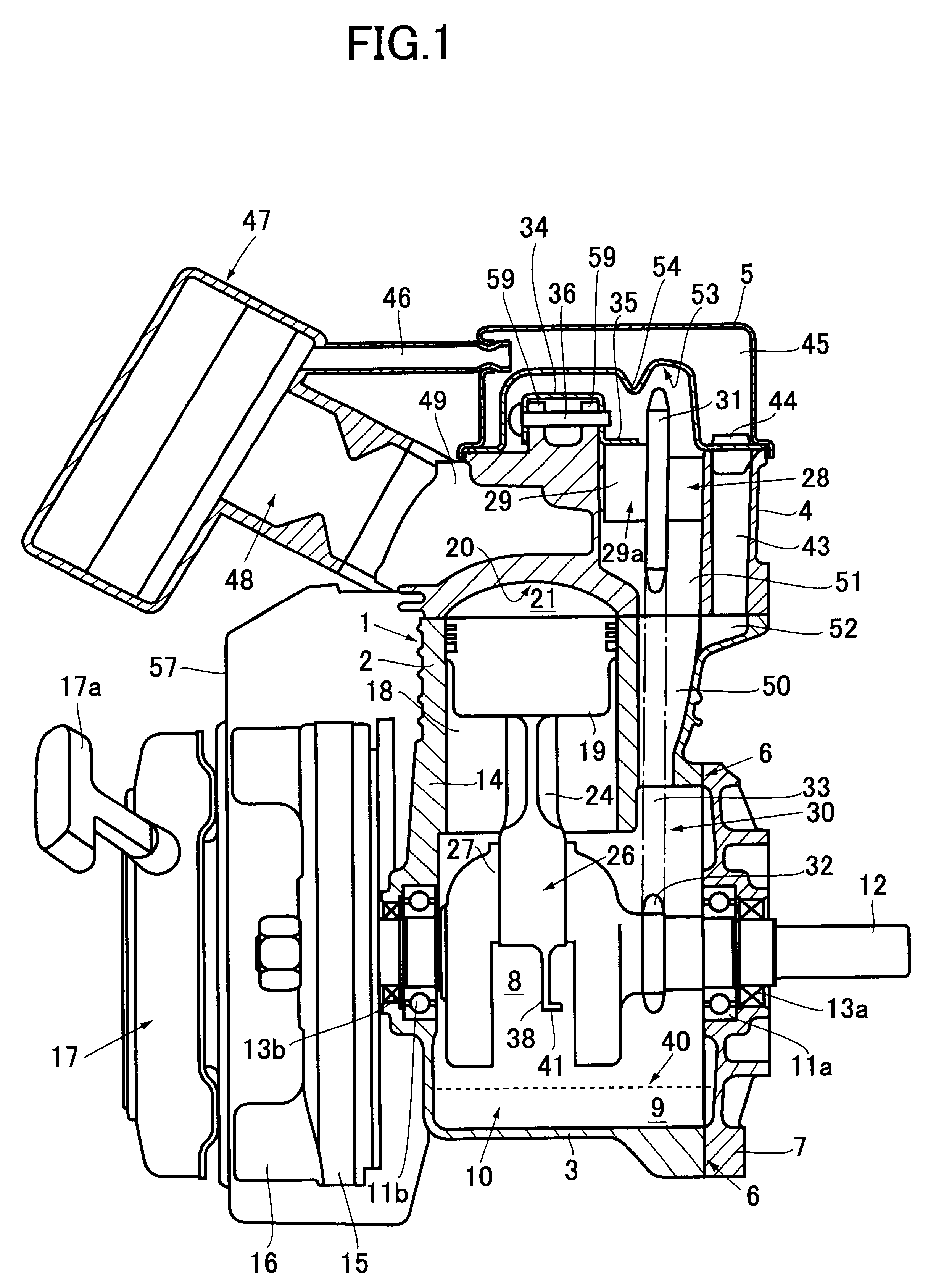
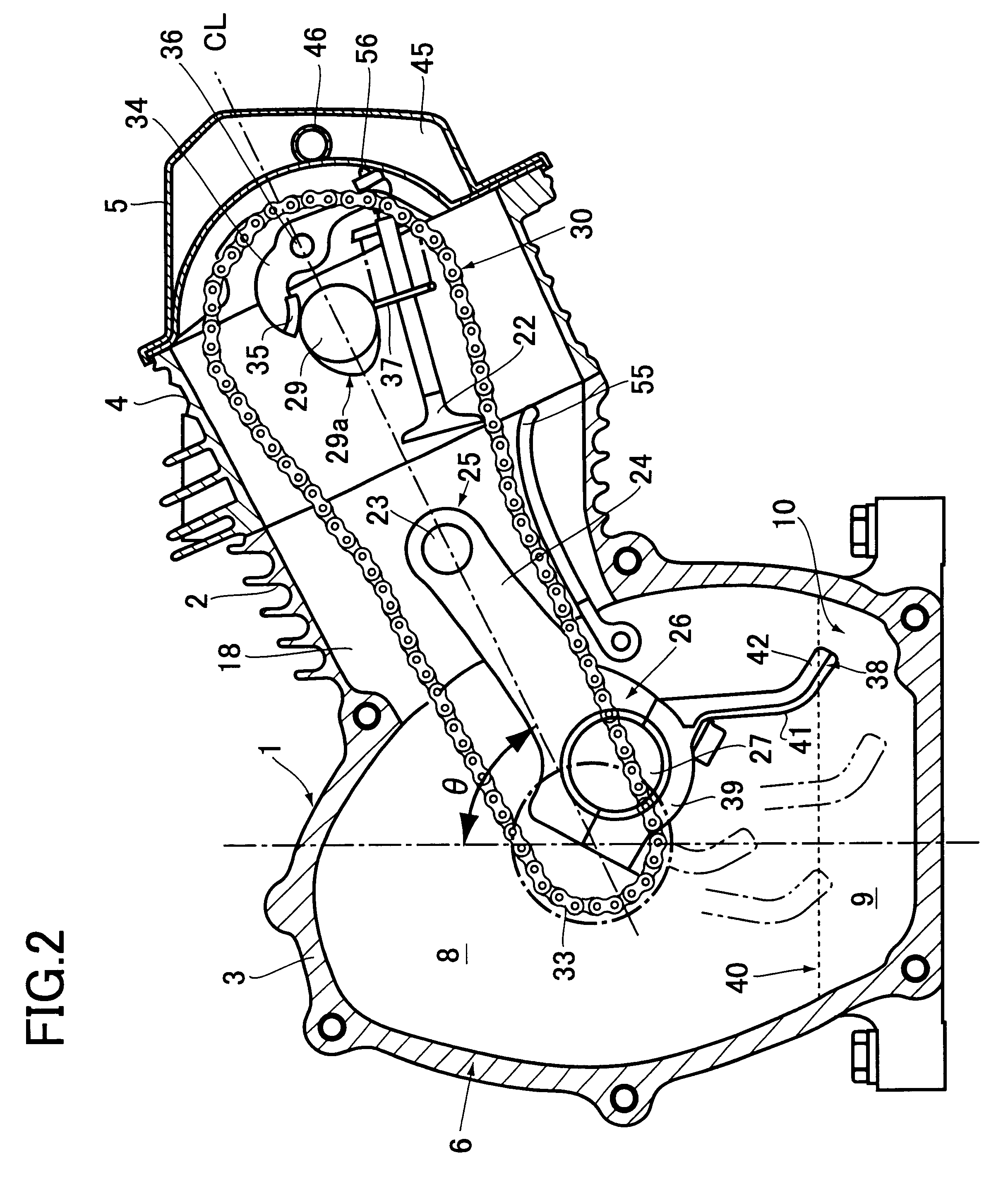
An embodiment of the present invention will now be described in detail with reference to the drawings. FIG. 1 is a diagram illustrating a structure of an OHC engine using a lubricating system of a valve-operating device in one embodiment of the present invention. FIG. 2 is an explanatory cross-sectional view of the engine of FIG. 1 taken along the cylinder axis direction.

The engine of FIG. 1 is a single-cylinder 4-cycle gasoline engine, and is a so-called "inclined type of OHC engine" in which the cylinder axis CL is inclined by an angle .theta. with respect to the gravitational direction (see FIG. 2). In this engine, an engine body 1 includes a cylinder block 2 and a crank case 3 which are integrally formed therein. The engine body 1 is made of iron or a light metal alloy such as an aluminum alloy. A cylinder head 4 made of an aluminum alloy is attached to an upper portion of the cylinder block 2. A rocker cover 5 made of a sheet metal or a synthetic resin is mounted on a top of th...


PUM


Abstract

A scraper is provided in a large end portion of a connecting rod in an inclined type of overhead camshaft engine to lubricate a timing system by dipping a lubricating oil stored in a lower portion of a crank case up. The scraper includes a bottom wall and a side wall set up on the bottom wall, and have a substantially L-shaped cross-section. An angle between the bottom wall and the side wall is set in a range of 60.degree. to 90.degree.. Thus, the droplets of the oil can be splashed to the side direction of scraper also in three-dimensional inclined direction, so that oil can be securely supplied to and lubricate the timing system which is offset from the scraper in a longitudinal direction of the crankshaft.

Description

BACKGROUND OF THE INVENTIONThe present invention relates to a lubricating system for an overhead camshaft engine (hereinafter referred to simply as "OHC engine"), in particular, to an effective technique applied to the OHC type of general-purpose engine, a cylinder axis of which is located with an inclination with respect to the gravitational direction.In the prior art, an overhead valve (hereinafter referred to simply as "OHV") and OHC type of general-purpose engines have been widely used as power sources for mowers, power sprayers, power generators, etc. For example, Japanese Patent Application Laid-open Publication No. Hei. 10-280932 discloses an engine of the OHV type, a cylinder axis of which is inclined in order to realize a compact size of the system. Further, Japanese Patent Application Laid-open Publication No. Hei. 8-177441 discloses an engine of the OHC type, an oil dipper of which rotates together with a crankshaft to improve a lubricating performance for a valve-operati...

Claims


Application Information

Patent Timeline
IPC IPC(8): F02B75/16F01M1/04F02B75/00F01M1/00F02B63/02F02B63/00F01M9/06F02B67/04F01M9/10
CPCF01M1/04F02B75/16F02B63/02F01M9/06F02B2275/20
Inventor FURUYA, AKIRASAKAI, TAKAO
Owner SUBARU CORP
Learn More