Display device for presentation of goods

a technology for displaying devices and goods, applied in the field of display devices, can solve the problems of not meeting every aesthetic requirement, not visually advantageous, and the bulkyness of rods and hangers, and achieve the effects of stable support capability, rapid change, and low cos

Inactive Publication Date: 2003-05-13
VISPLAY INT AG
View PDF22 Cites 51 Cited by
  • Summary
  • Abstract
  • Description
  • Claims
  • Application Information

AI Technical Summary

Benefits of technology

In view of the imperfections and limited possibilities of use of the display device existing to date, the invention is based on the problem of providing an improved display device which allows great variability, has a sturdy supporting capability, permits rapid changing around of the equipment, securely supports the goods even when business is brisk and meets diverse, aesthetic requirements. The shaped rods used are to be of the simplest possible cross section, and also the supporting arms are to have an uncomplicated design so that the entire device can be produced inexpensively and can be changed in a flexible manner. If the width of the shaped rod is a multiple of the width of the supporting arms, the latter are to be fitted at any desired horizontal position along a shaped rod--i.e. in an entirely freely selectable manner or within a grid--and then securely mounted. In a design variant, the shaped rods are intended as short pieces to be able to be arranged in a grid shape in lines and rows on a panel. One thing to be avoided is that [lacuna] shaped rods which are not fitted with fitted supporting arms open, irregular slot sections can be visible.

Problems solved by technology

A large part of the slot surface, which remains unoccupied, is freely visible, which is not visually advantageous.
The shaped rods and hanger parts are relatively bulky components and so these devices do not meet every aesthetic requirement.
In this case, either complicated, rough shapes and relatively complex supporting arms are used or the slot surfaces, which for the most part are unoccupied, are externally visible.

Method used


Image

  • Display device for presentation of goods
  • Display device for presentation of goods
  • Display device for presentation of goods

Examples


first embodiment

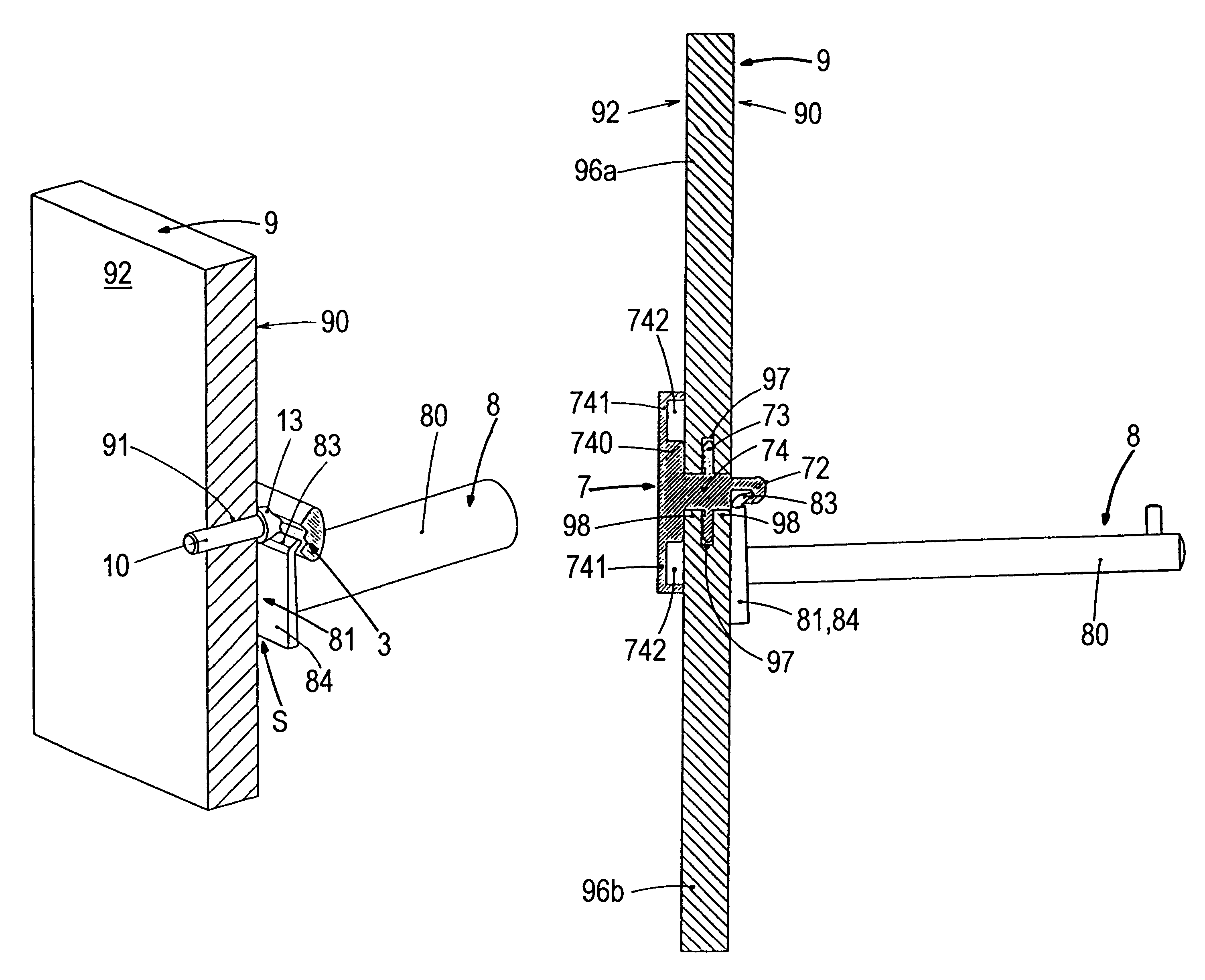
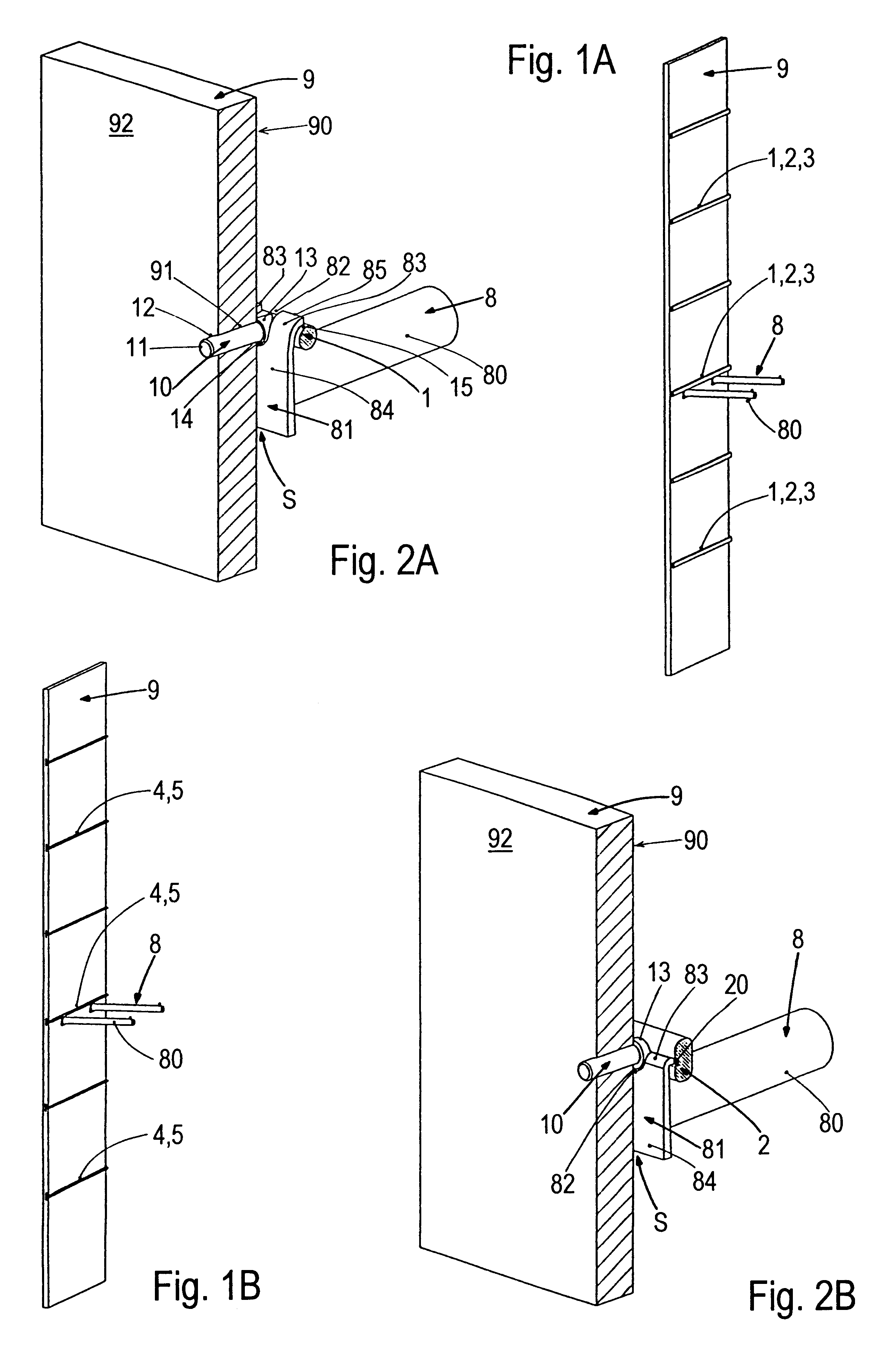
In the display device the shaped rod 1, which is placed onto the front side 90 of the supporting structure 9, has a round cross section. A plurality of bolts 10 which lie in a plane and protrude through through-holes 91 present in the supporting structure 9 extend perpendicularly from the longitudinal axis of the shaped rod 1. An external thread 12 is preferably provided on the free bolt end 11 so that a nut (not shown) can be screwed from the rear side 92 of the supporting structure 9 onto the protruding-through bolt end 11 for the purpose of fastening the shaped rod 1. Arranged opposite the free bolt end 11 is a thickened portion 13 which results in an annular shoulder 14 facing the free bolt end 11. The thickened portion 13 can be produced by a corresponding design of the bolt 10 or by a spacer sleeve pushed onto the bolt 10. The shoulder 14 has a larger external diameter than the through-hole 91 and is therefore placed on the front side 90 of the supporting structure 9 so that t...

second embodiment

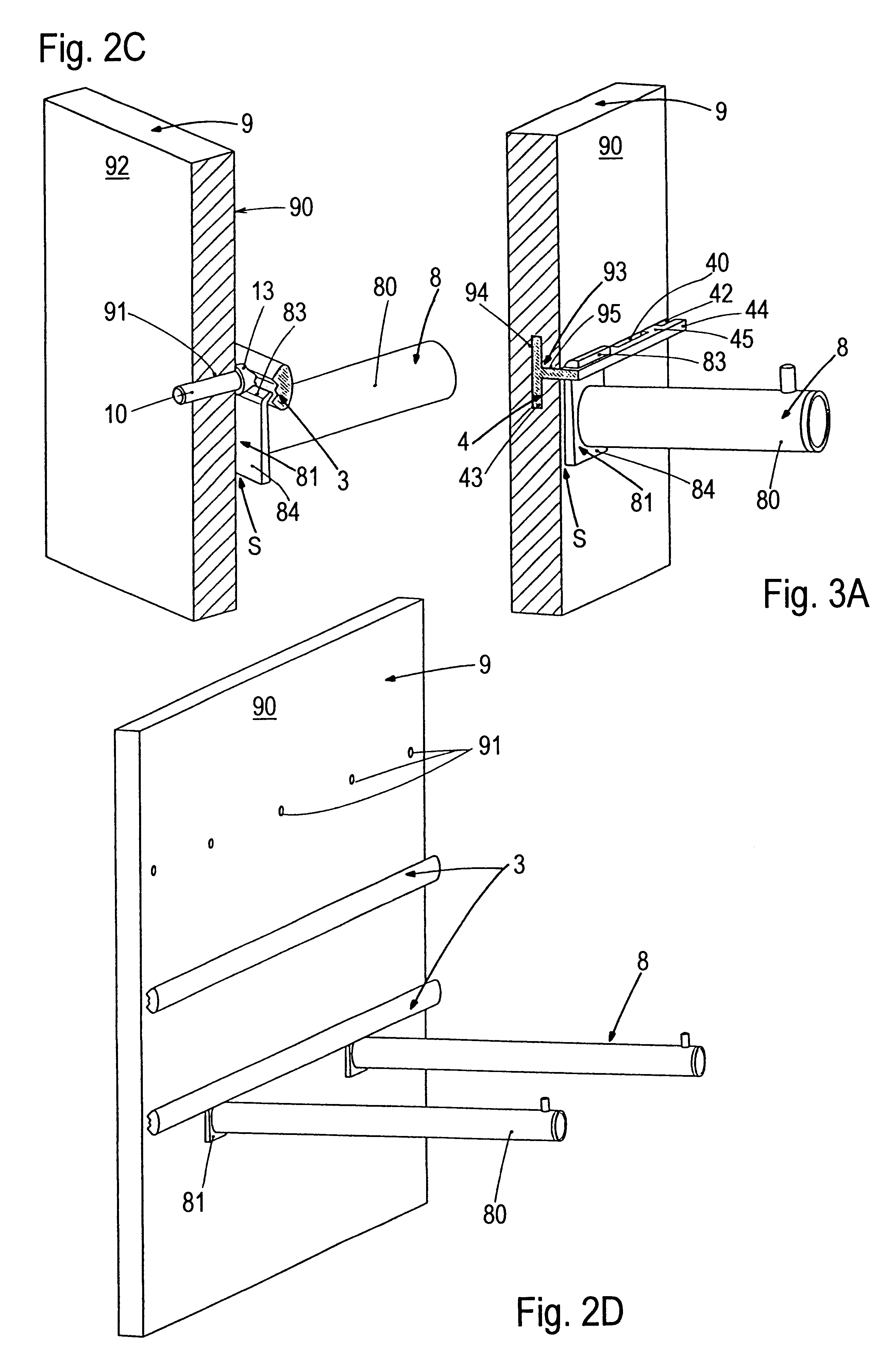
The second embodiment is different from the preceding figure only with regard to the cross section of the shaped rod 2, a plug-in groove 20 provided therein, the bending of the tongues 83 and the engagement of the tongues 83 into the plug-in groove 20. The shaped rod 2 has an oval cross section in principle, but only constitutes an alternative to the round shaped rod 1 and is otherwise insignificant. The shaped rod 2 could also have a round cross section. The essential feature is the axial plug-in groove 20 which faces the front side 90, runs along the shaped rod 2 and extends horizontally into the shaped rod 2. The indentation 82 on the plug-in plate 81 is less deep and the bending radius in which the tongues 83 are turned towards the rod part is smaller. In this case, the tongues 83 are in principle bent away at right angles so that the tapering-off parts of the tongues 83 have a horizontal alignment.

In the fitted state the plug-in plate 81 is again situated in the gap spacing S, ...

third embodiment

The third embodiment again has a cross-sectionally differently contoured shaped rod 3 and different bending of the tongues 83. The shaped rod 3 is approximately oval in cross section and on the side which faces the front side 90 of the supporting structure 9 has at least one oblique surface 30 which extends longitudinally axially of the shaped rod 3 and ascends from the lower half of the shaped rod 3 towards the horizontal central axis M of the shaped rod 3 at a pitch angle .alpha.. A further oblique surface 31 is preferably provided, this surface descending from the upper half of the shaped rod 3 towards the horizontal central axis M of the shaped rod 3 at a pitch angle .alpha.. Only the lower oblique surface 30 is required for the fitting of the supporting arms 8. The symmetrical arrangement of the oblique surfaces 30,31 makes it possible also to place the shaped rod 3 turned through 180.degree. onto the front side 90 of the supporting structure 9 so that then the oblique surface ...


PUM


Abstract

A display device for presentation of goods includes a support panel and a horizontal rod with a longitudinal groove fixed to the panel. Supporting arms with a rod part extending from a plate with bent tongue are attached to the horizontal rod by hooking the tongue into the longitudinal groove from underneath. In an alternative embodiment, the plate may have a hook that hooks into a slot provided on an upper surface of the rod. The supporting arms may support goods or shelves.

Description

FIELD OF USE OF THE INVENTIONThe present invention relates to a display device for the presentation of goods in shops and at exhibitions. The display device comprises a supporting structure, for example a panel, at least one shaped rod fixed horizontally on the supporting structure and supporting arms which can be fitted into this shaped rod. In general, the display device has a plurality of shaped rods which are arranged systematically spaced apart from one another horontally. The supporting arms can be fitted as desired within all selectable positions and serve for the direct or indirect support of the goods to be displayed. A typical use is provided in the clothing sphere where outer clothing garments hanging on hangers are hung onto display devices fitted with supporting arms. Display devices of this type make possible presentation of the offered goods close to the customer, design of the selling areas to be variable and uncomplicated changing of the fitments. Nevertheless, the ...

Claims


Application Information

Patent Timeline
Patent Type & Authority Patents(United States)
IPC IPC(8): A47F5/08
CPCA47F5/0853A47F5/0815
Inventor WALTER, HERBERTUECKER, MANFRED
Owner VISPLAY INT AG
Why Eureka
Try Eureka