Axial securing device for two components by means of a locking ring

a technology of locking ring and locking ring, which is applied in the direction of hose connection, rod connection, shock absorber, etc., can solve the problems of difficult to tell from the outside whether the locking ring is secure, and it is impossible to repeat the assembly procedur

Inactive Publication Date: 2003-05-13
ZF FRIEDRICHSHAFEN AG
View PDF25 Cites 24 Cited by
  • Summary
  • Abstract
  • Description
  • Claims
  • Application Information

AI Technical Summary

Benefits of technology

The advantage of this measure is that a locking ring, which could not be inspected or accessed in any way after it had assumed its final position, can now be installed reliably. If the locking ring cannot assume its intended final position immediately as a result of an unfavorable combination of tolerances of the parts to be connected, this condition can be remedied by means of a simple tool.
To improve the retaining effect of the locking ring, the part of the tool which rests radially against the locking ring has a shoulder at the end facing the open end of the hollow cylindrical body, this shoulder representing a contact surface for the locking ring. The locking ring thus cannot be pulled into the ring-shaped space under load.
To facilitate the installing movement of the tool onto the locking ring, the diameter change section has a conical surface, which comes to rest against a lateral surface of the tool.
For the purpose of minimizing the contact pressure, at least a certain section of the tool also has a conical lateral surface, which conforms to the conical surface of the diameter change section.
In a further advantageous design, the tool has a circumferential collar, which comes to rest against an axial, ring-shaped end surface on the hollow cylindrical body after the tool has been inserted to the maximum extent. This prevents the tool from being pushed into the ring-shaped space beyond a reasonable distance.
The tool can also be considered a "lost" part, which remains in the ring-shaped space after assembly. The advantage of this measure is that the tool cannot be removed by tinkerers from the ring-shaped space without damage and thus serves as a safety device to protect against unwanted manipulation of the axial securing device.

Problems solved by technology

The problem is that it is difficult to tell from the outside whether the locking ring has in fact assumed its intended final position.
Within the scope of industrial fabrication, it is possible to check the results of the step, but it is impossible to repeat the assembly procedure.

Method used


Image

  • Axial securing device for two components by means of a locking ring
  • Axial securing device for two components by means of a locking ring
  • Axial securing device for two components by means of a locking ring

Examples


Embodiment Construction

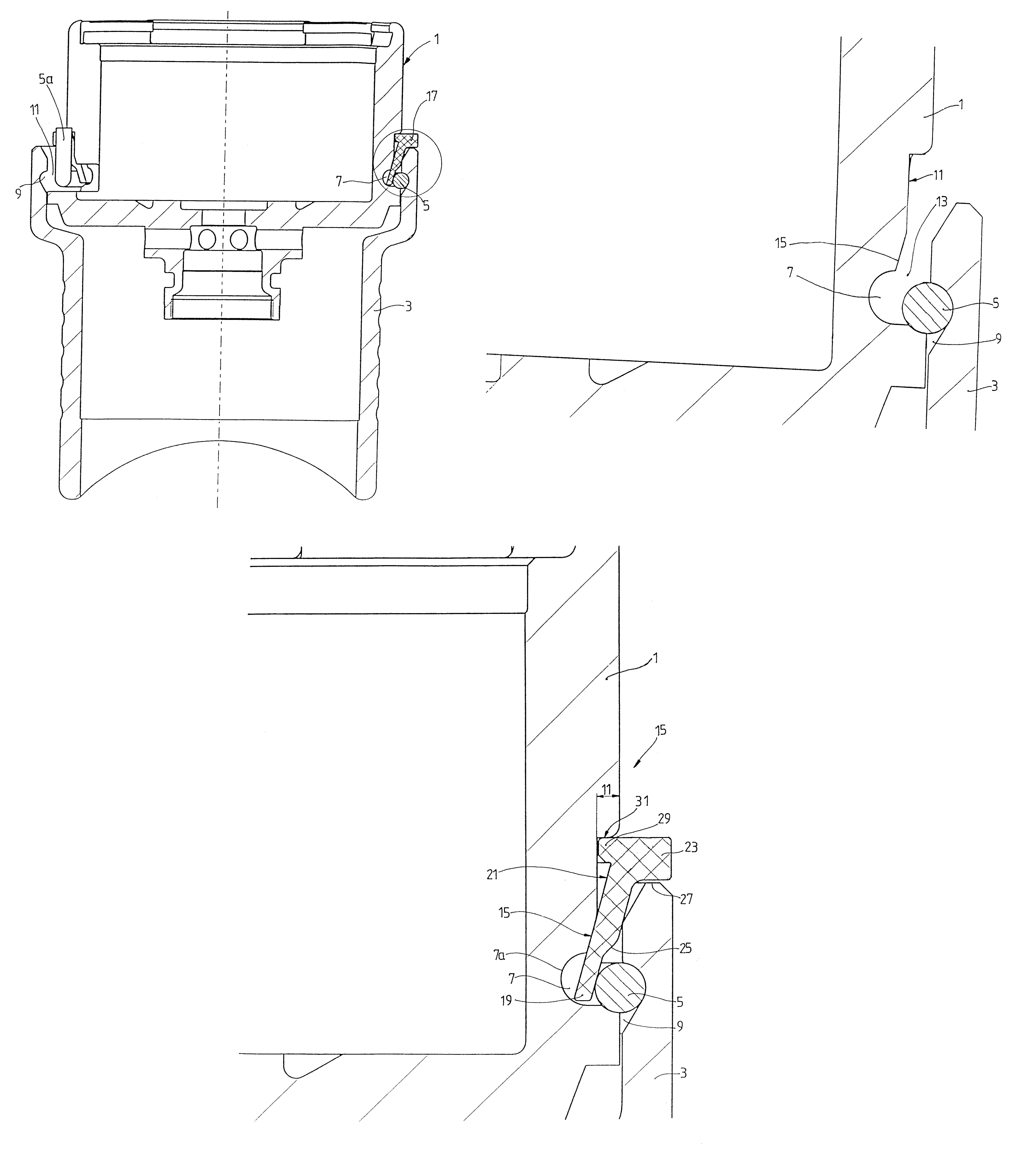
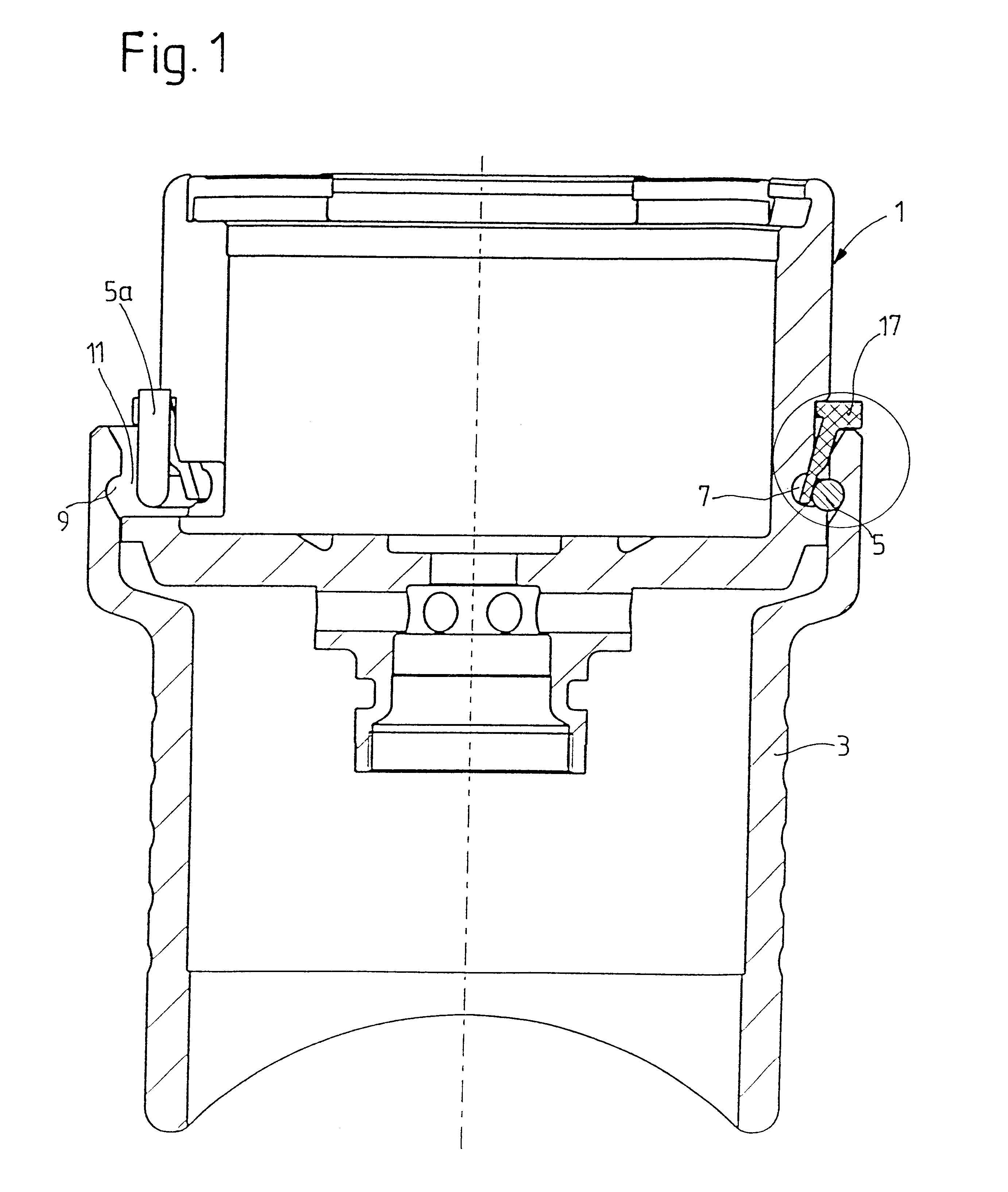
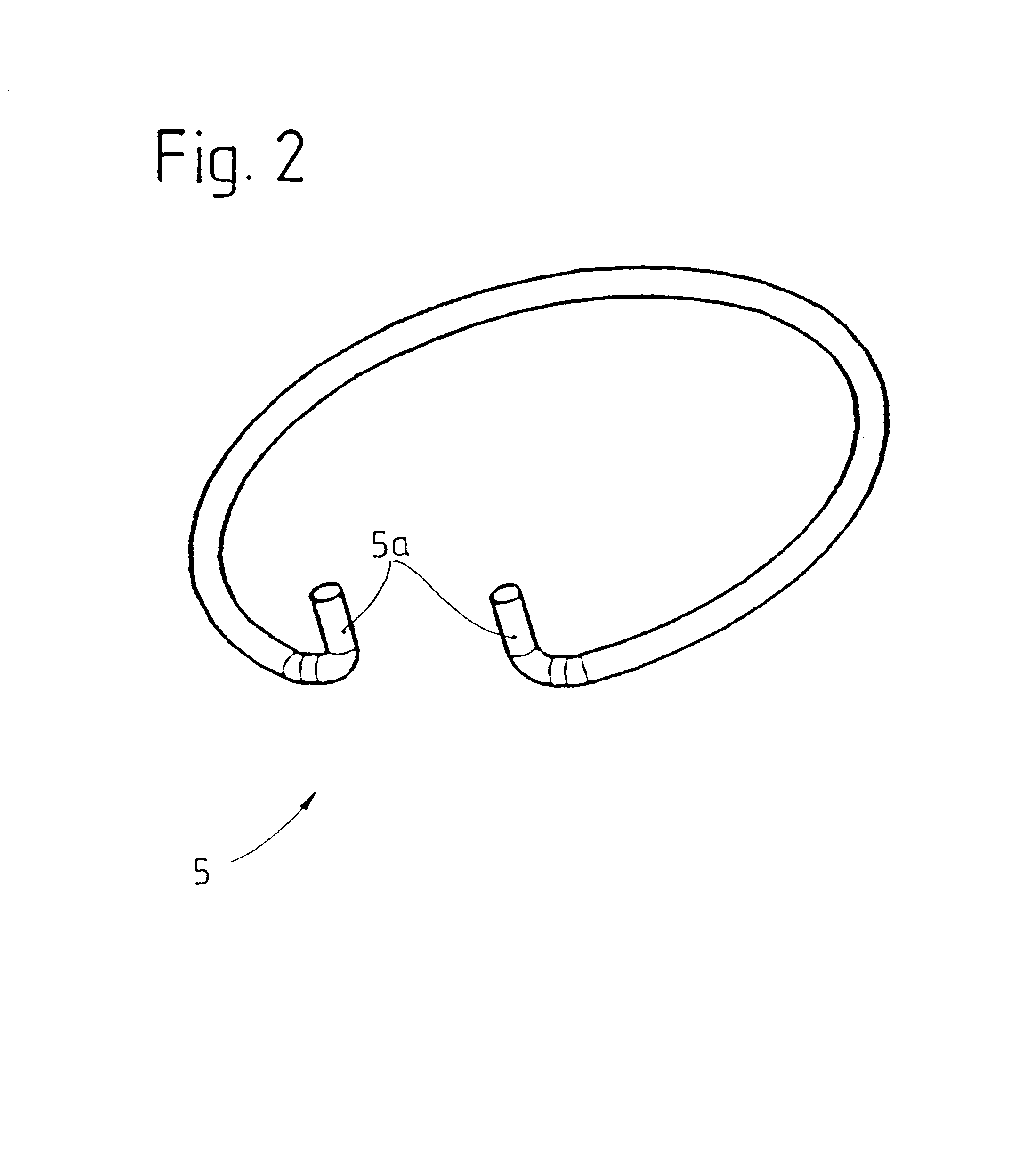
FIG. 1 shows the cylindrical component 1. In this case, the component is a receptacle for a valve, but the application of the invention is in no way limited to this application. This receptacle is designed to be inserted into a hollow cylindrical body 3. A locking ring 5 has the job of locking the two cylindrical components together axially. In FIG. 2, the locking ring is shown as an individual part, so that the bent ends 5a provided to facilitate installation can be seen more clearly. The bent ends can be squeezed together with simple pliers, so that the locking ring can be inserted into a groove 7 in the cylindrical component 1. Then the cylindrical component with the compressed locking ring 5 is guided into the open end of the hollow cylindrical body, so that the locking ring can now lock itself into the groove 9 in the hollow cylindrical body.

As can be seen in FIG. 3, which shows a part of FIG. 1, a circumferential ring-shaped space 13 is created by a diameter change section 11,...


PUM


Abstract

An open end of a hollow cylindrical body receives part of a cylindrical component, where the hollow cylindrical body and the cylindrical component each having a groove, the grooves being aligned when the cylindrical component is in its intended final position with respect to the hollow cylindrical body, so that a locking ring is captured by the two grooves. The cylindrical component works together with the hollow cylindrical body to form a ring-shaped space, which extends from one of the two grooves toward the open end of the hollow cylindrical body, thus offering access for a tool to move the locking ring into its intended final position.

Description

1. Field of the InventionThe invention pertains to an axial securing device for a cylindrical component received in the open end of a hollow cylindrical body, each part having a groove which aligns with the groove of the other part to capture a locking ring between the grooves.2. Description of the Related ArtU.S. Pat. Ser. No. 6,044,939 discloses an adjustable valve, the receptacle of which is locked axially in place in a socket piece, designed as a hollow cylindrical body, by a locking ring. The receptacle has a circumferential groove, which accepts the entire locking ring as the receptacle is pushed into the socket piece. Once the receptacle has reached its intended final position, this groove lines up with another groove in the socket piece. The locking ring can then expand radially and thus assumes a diameter which overlaps the grooves in the socket piece and in the receptacle. Thus the receptacle is secured axially inside the socket piece.The problem is that it is difficult to...

Claims


Application Information

Patent Timeline
Patent Type & Authority Patents(United States)
IPC IPC(8): F16B21/18F16B21/00F16F9/32
CPCF16B21/183F16F9/325Y10T403/7051Y10T403/7016Y10T403/5793Y10T403/4949Y10T403/557Y10T403/7049Y10T403/4966Y10T403/7052
Inventor WIRTH, ALFREDKEIDEL, ANDREASHEYN, STEFFEN
Owner ZF FRIEDRICHSHAFEN AG
Why Eureka
Try Eureka