Magnetic fixing unit

a technology of fixing unit and fixing plate, which is applied in the direction of magnets, magnet bodies, coins, etc., can solve the problems of deformation or weakening, uneven thickness of annular projection portion, and inability to achieve smooth engagement and disengagemen

Inactive Publication Date: 2003-05-20
MORITA TAMAO
View PDF19 Cites 48 Cited by
  • Summary
  • Abstract
  • Description
  • Claims
  • Application Information

AI Technical Summary

Benefits of technology

The object of the present invention is to improve the operation of prior magnetic fixing units preventing a mutual shifting between its first and second assemblies, and simultaneously reinforcing the strength of the assemblies without spoiling the fixing units exterior appearance.
According to one aspect of the present invention, a magnetic fixing unit is provided with a first assembly which is attached to one member of a pair of members which are to be attached, and a second assembly is attached to the other member of said pair of members. The first and said second assemblies are attracted and combined with each other at their attaching surface by the operation of a magnet disposed on either said first or second assemblies. Moreover, the first assembly comprises an engaging means projected from its attracting surface. Which said second assembly comprises an internal guide means so as to facilitate the entry and receipt of said engaging means into said guide means when the first and the second assemblies are combined with each other. In addition, said second assembly is provided with means to lock said engaging means to said second assemblies when said first and second assemblies are combined with each other. Finally, a release means to release said lock means is provided.

Problems solved by technology

If the strength of the metallic assemblies is weak, they may be deformed or weaken by the affixing process.
This shift can cause a problem when an attempt is made to disengage the assemblies because the lateral shift of the projection of the first assembly within the hole of the second assembly can cause it to catch within the second assembly and as a result, a smooth engagement and disengagement may not be achieved.
One such shortcoming is that the thickness of the annular projecting portion may become an obstacle when a purse is opened.
Another shortcoming is that the appearance the fixing unit gives is an undesirable thick appearance.
Thus the manufacturers are faced with the undesirable choice of including the annular projecting portion to order to prevent the mutual shifting but if that is done, you end up with an undesirable looking exterior.

Method used


Image

  • Magnetic fixing unit
  • Magnetic fixing unit
  • Magnetic fixing unit

Examples


Embodiment Construction

There will now be described several preferred embodiments of the present invention.

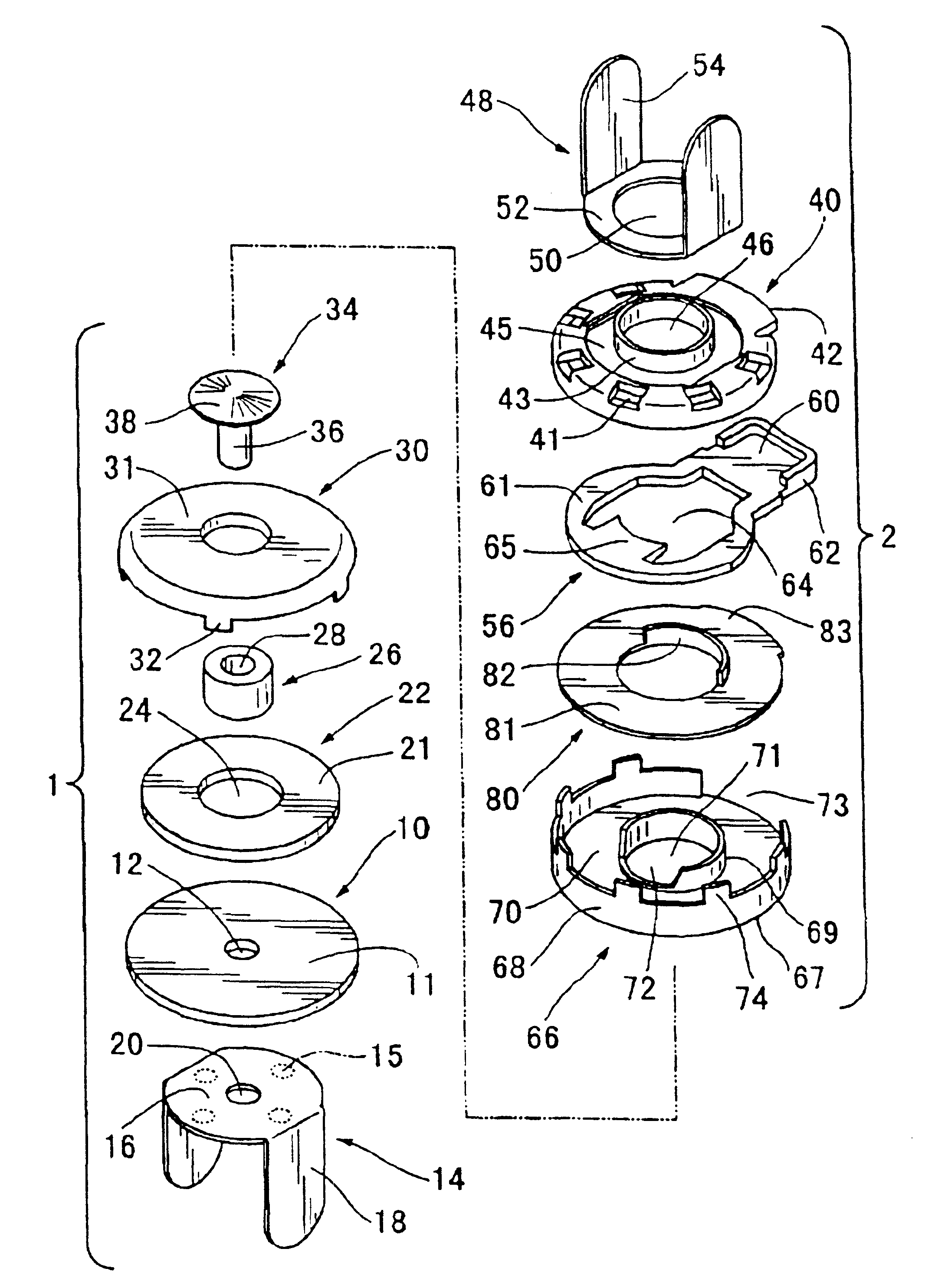
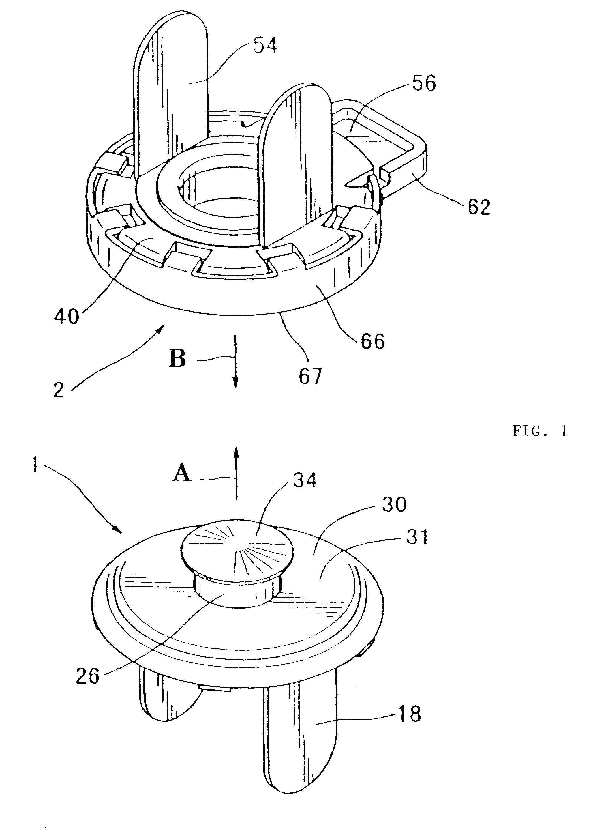
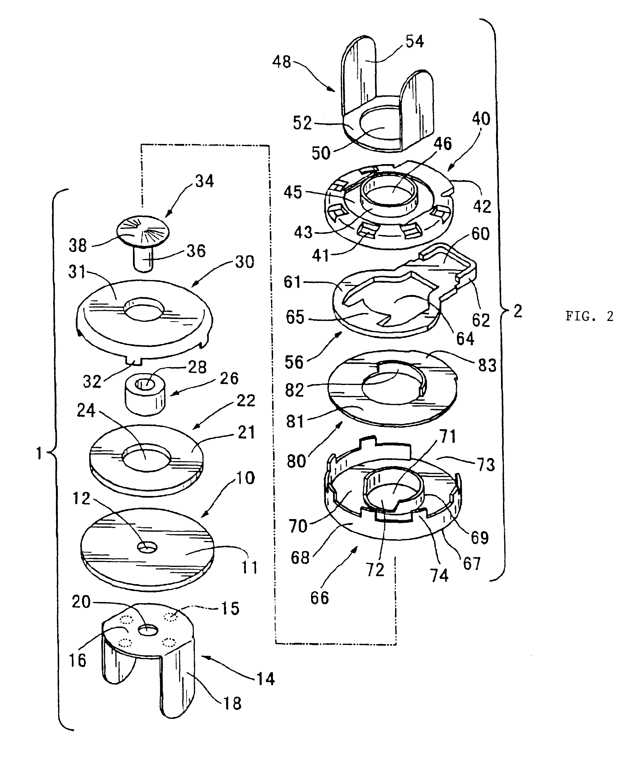
FIG. 1 is a perspective view of an assembled magnetic fixing unit according to the present invention. As shown in the drawings, the magnetic fixing unit of the present invention comprises a first assembly 1 and a second assembly 2. Each of these pairs of assemblies is, as described later, fixed respectively to one of a pair of mating members (for example, a main body and a lid of a handbag) of an object to be equipped with said magnetic fixing unit. These assemblies are movable in the combination direction of the first and the second assemblies, as shown in FIG. 1, by the arrows A & B, such that the assemblies will be attracted and combined with each other at respective attracting surfaces 31 and 67. As a result, the mating members of a handbag, for example, will be kept in a closed condition. In the magnetic fixing unit of this invention, the first and the second assemblies will not only be combined ...


PUM

PropertyMeasurementUnit
thicknessaaaaaaaaaa
angleaaaaaaaaaa
angleaaaaaaaaaa

Abstract

A magnetic fixing unit having a first and second sub-assembly with cooperative structure for increased strength of assembly and prevention of mutual shifting between the first and the second assemblies. The magnetic fixing unit further includes a guide structure on one of the first and second assemblies to effect cooperative locking engagement with an engaging member on the other of the assemblies.

Description

The present invention relates to a magnetic fixing unit, in particular, to a simplified magnetic fixing unit capable of automatically locking, for example, a handbag in a closed condition.PRIOR ARTIn order to keep the lid of, for example, a handbag, gag, knapsack, belt, or an attache case, in a closed condition, various kinds of fixing units have been designed and are available. One of them is a magnetic fixing unit using magnetic force.An example of a magnetic fixing unit, described above, is shown in official Report No. 2944564 patent applied Heiseil 194638 which was applied for by the applicant of this patent application. This magnetic fixing unit comprises a first assembly which is attached to one member of a pair of members which have to be joined together, and a second assembly which is attached to the other member of said pair of members. The pair of members can be, for example, a handbag lid and a main body of a handbag. The above first and second assemblies are capable of n...

Claims


Application Information

Patent Timeline
Patent Type & Authority Patents(United States)
IPC IPC(8): A45C13/10H01F7/02
CPCA45C13/1069A45C13/1084H01F7/0263A45C13/1092Y10T24/3679Y10T24/1959Y10T24/32Y10T292/11
Inventor MORITA, TAMAO
Owner MORITA TAMAO
Why Eureka
Try Eureka