
Portable air-borne bacteria sampler

a microorganism and sampler technology, applied in auxillary pretreatment, instruments, separation processes, etc., can solve the problems of difficult to conduct the measurement at any place, liable to be large in size and heavy in weight, and high static pressure cannot be achieved

Inactive Publication Date: 2003-05-20
MIDORI ANZEN
View PDF5 Cites 29 Cited by
  • Summary
  • Abstract
  • Description
  • Claims
  • Application Information

AI Technical Summary

Benefits of technology

It is another object of the invention to provide a small and light portable type airborne microorganism sampler, which can solve the above problem (2) and can collect airborne microorganisms positively without contaminating a surrounding environment.
It is another object of the invention to provide a portable type airborne sampler, which can solve the above mentioned problem (3), can produce a uniform air flow through a nozzle portion per unit surface area thereof, and can measure precisely the number and positions of colonies produced after collection and cultivation.

Problems solved by technology

(1) In the known air sampler mentioned above, the stationary type sampler has a sufficiently high collection efficiency, measured by JIS method, because the measurement is carried out under the JIS method, but it uses a large suction pump, and therefore it is liable to be large in size and heavy in weight.
Moreover, AC 100V power supply is required as the main power, and therefore it is difficult to conduct the measurement at any place.
Although the portable type air sampler can be small in size and light in weight by using a small fan such as sirocco fan and radial fan, a high static pressure could not be attained.
Therefore, in order to introduce a sufficiently large air-flow rate through the nozzle portion 4, the nozzle openings have to be configured such that the sampler can operate under a low static pressure, but this makes a collection efficiency low.
In the known airborne microorganism sampler, these particles and droplets are spread out of an exhaust port of the sample together with an air flow and might contaminate a clean room.
In a place where a larger air-flow rates, the culture medium is liable to be dried to decrease a collection efficiency and even after the incubation, a colony is hardly formed.

Method used


Image

  • Portable air-borne bacteria sampler
  • Portable air-borne bacteria sampler
  • Portable air-borne bacteria sampler

Examples


Embodiment Construction

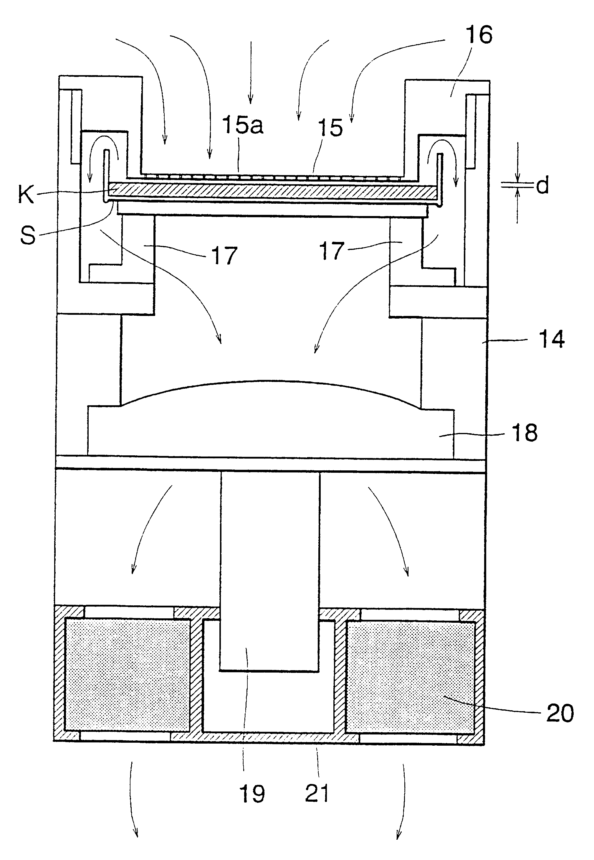
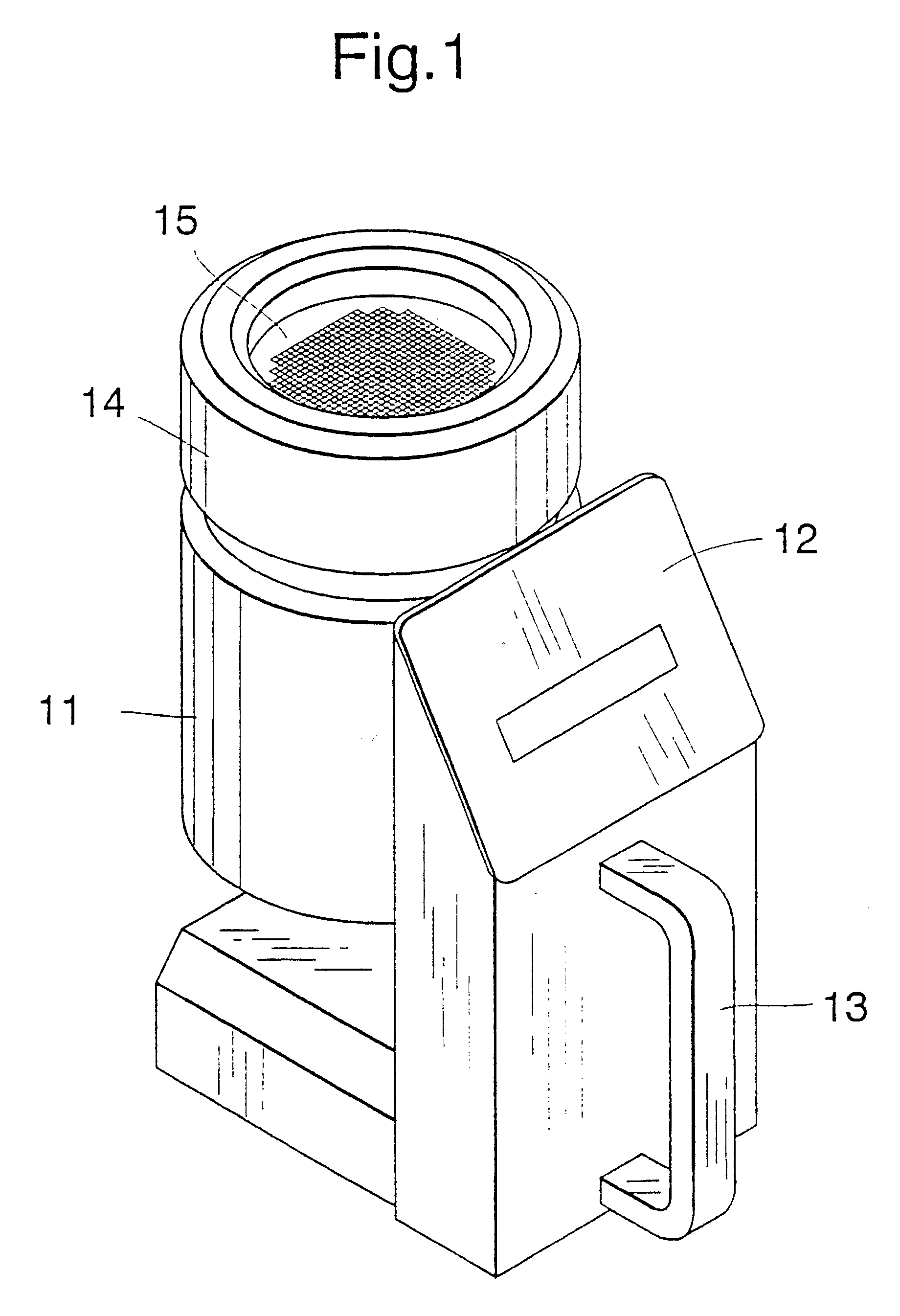
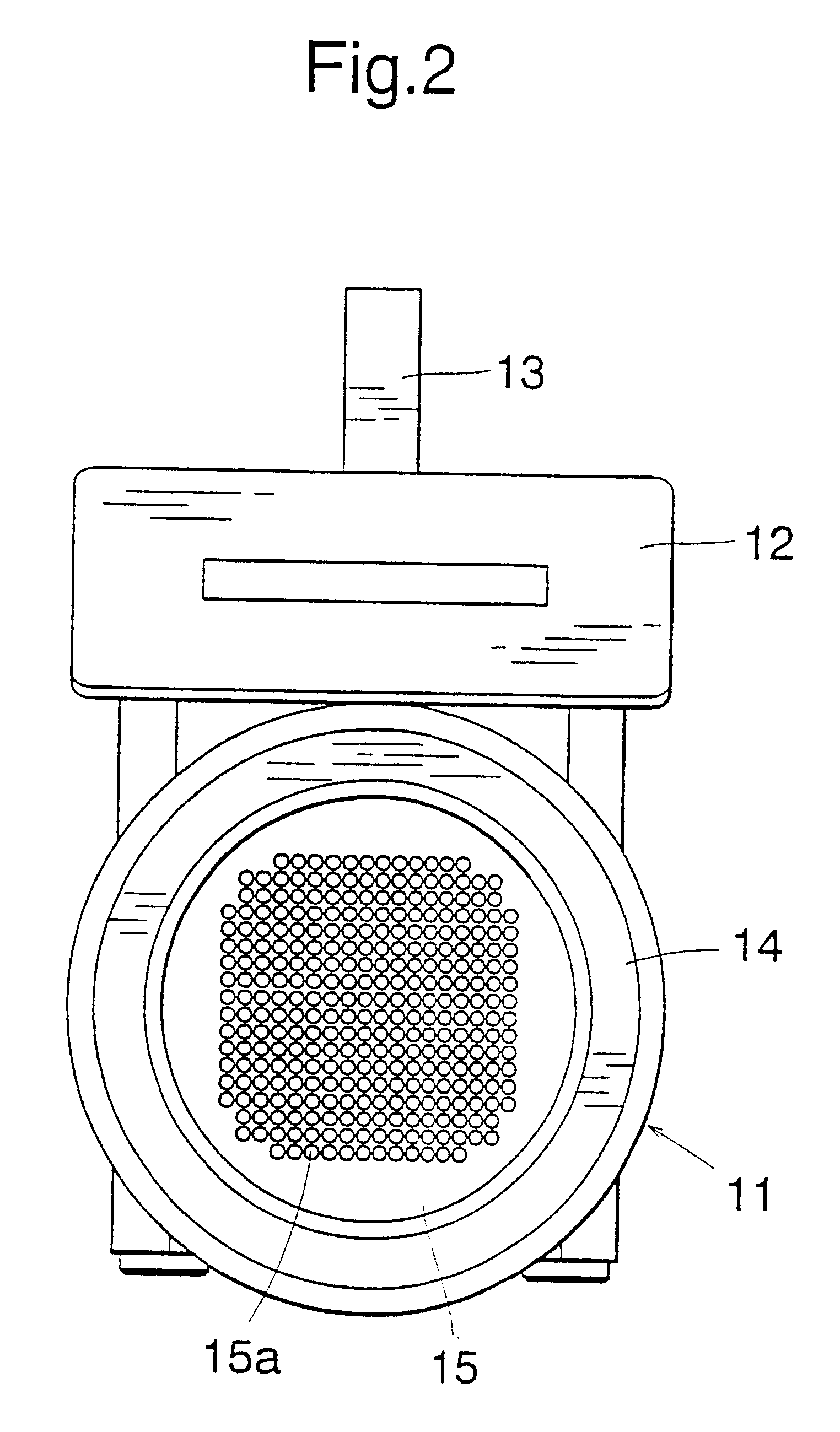
FIG. 1 is a perspective view showing the portable type airborne microorganism sampler according to the invention, FIG. 2 is a plan view thereof, and FIG. 3 is a cross sectional view thereof. The portable type sampler is mainly composed of a collecting section 11 for collecting airborne microorganisms and an operating section 12. The operating section 12 includes a grip 13 for carrying the sampler. The collecting section 11 comprises a cylindrical housing 14 and a nozzle 15 having a number of fine nozzle openings 15a formed therein, said nozzle being supported by a nozzle support 16 at a top of the housing 14 as illustrated in FIG. 4. The nozzle openings 15a are arranged in a grid-like manner, and an opening is formed by a straight tube portion 15b having a diameter of 0.36 mm and a height of 0.5 mm and a tapered portion 15c having a open angle of 90 degrees and a height of 0.5 mm as depicted in FIG. 5, the taped portion serving to reduce a pressure loss in the nozzle 15.

In order to ...


PUM

PropertyMeasurementUnit
air-flow velocityaaaaaaaaaa
static pressureaaaaaaaaaa
air-flow velocityaaaaaaaaaa

Abstract

After supporting a petri dish S having a culture medium K contained therein with a given thickness on a petri dish holder 17 of a housing 14, a nozzle holder 13 is clamped at a top of the housing 14. When a motor 19 is energized to rotate a high static pressure fan 18, air is introduced through nozzle openings 12a, and flows through a space between the nozzle 15 and the culture medium K. By setting a distance between the nozzle and the culture medium to 0.5-1.5 mm, a high collection efficiency can be attained.

Description

The present invention relates to a portable type airborne microorganism sampler for collecting airborne microorganisms in a room for monitoring and managing a pollution due to microorganisms and bacteria and fungi.FIG. 1 is a perspective of the sampler;FIG. 2 is a plan view thereof;FIG. 3 is a cross sectional view thereof;FIG. 4 is a side view of a nozzle;FIG. 5 is a cross sectional view of an opening of the nozzle;FIG. 6 is an actual and ideal impactor cutoff curves.FIG. 7 is a graph representing a relationship between a culture medium-nozzle distance and a collection efficiency;FIG. 8 is a graph denoting a relationship between a air-flow velocity through the nozzle and a collection efficiency;FIG. 9 is a perspective view showing a radially pleated filter;FIG. 10 is a perspective view illustrating a parallelly pleated filter; andFIG. 11 is a plan view showing a known sampler.TECHNICAL BACKGROUNDThere have been proposed a stationary type airborne microorganism sampler and a portable...

Claims


Application Information

Patent Timeline
Patent Type & Authority Patents(United States)
IPC IPC(8): C12M1/26
CPCG01N1/2273G01N1/2205G01N2001/2276
Inventor SUGITA, NAOKIHATTA, YUTAKAYAMADA, TAKESHINAKATA, YUKIHIRO
Owner MIDORI ANZEN
Learn More