Image processing apparatus
a technology of image processing and apparatus, applied in the field of image processing apparatus, can solve the problems of not being able to read, reducing the contrast of characters in background, and being very illegible, and not necessarily becoming legibl
- Summary
- Abstract
- Description
- Claims
- Application Information
AI Technical Summary
Benefits of technology
Problems solved by technology
Method used
Image

Examples
first embodiment
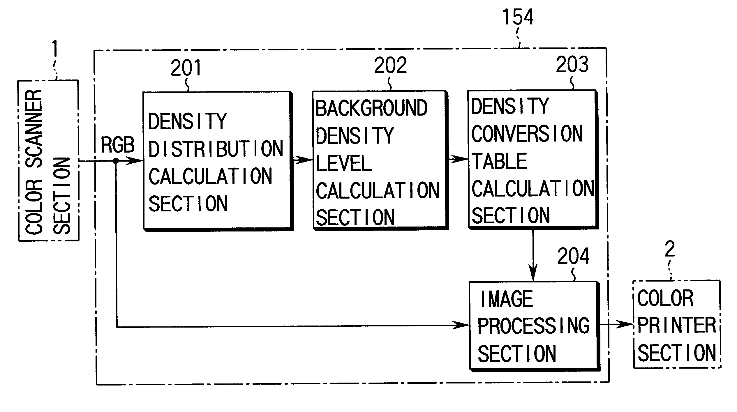
FIG. 4 shows an arrangement of a major section of an image processing apparatus according to the present invention. For brevity in an explanation in FIG. 4 et seq., those other than the image processing section 154 are omitted in illustration and will be explained below in this context.
In FIG. 4, the color image data, R, G, B output from the color scanner section 1 is sent to a density distribution calculation section 201 through the position matching interpolation section 151. The density distribution calculation section 201 calculates a density distribution of the color of the document as color features of the document on the basis of the input color image data R, G, B and a result of calculation is sent to a background density level calculation section 202. The background density level calculation section 202 calculates the background density level of the document on the basis of the density distribution calculated at the density distribution calculation section 201 and sends a r...
second embodiment
Next an explanation will be given below about the
In the first embodiment, the background density level is calculated while, on the other hand, the background density level is calculated in the second embodiment taking into consideration the broadening of the background density distribution.
FIG. 11 shows an arrangement of a major portion of an image processing apparatus 36 according to the second embodiment. The second embodiment is different from the first embodiment in that, in place of the background density level calculation section 202, use is made of a background density distribution calculation section 205. The other portion of the second embodiment is the same as that of the first embodiment and any further explanation is omitted with the same reference numerals employed to designate part and element corresponding to those shown in the first embodiment.
FIG. 12 shows a practical form of the background density distribution calculation section 205 and it comprises three comparat...
third embodiment
Then, a third embodiment will be explained below.
In the above-mentioned first and second embodiments, the image density is converted based on the density conversion table while, in a third embodiment, this is done through calculations all with the use of hardware.
FIG. 13 is an arrangement of a major portion of an image processing apparatus 36 according to a third embodiment. The third embodiment is different from the second embodiment in that the density conversion table preparing section 203 is eliminated and that, instead of the image conversion section 204, a background density conversion section 206 is used. The remaining portion is the same as that of the second embodiment and the same reference numerals are employed to designate parts or elements corresponding to those shown in the second embodiment and any further explanation is omitted.
FIGS. 14A and 14B show a practical form of the background density conversion section 206. In the case of FIG. 14A, it comprises a subtracter ...
PUM
 Abstract
Description
Claims
Application Information
 - Generate Ideas
- Intellectual Property
- Life Sciences
- Materials
- Tech Scout
- Unparalleled Data Quality
- Higher Quality Content
- 60% Fewer Hallucinations
Browse by: Latest US Patents, China's latest patents, Technical Efficacy Thesaurus, Application Domain, Technology Topic, Popular Technical Reports.
© 2025 PatSnap. All rights reserved.Legal|Privacy policy|Modern Slavery Act Transparency Statement|Sitemap|About US| Contact US: help@patsnap.com