
Battery pack

a battery pack and battery technology, applied in the field of batteries, can solve the problems of battery pack as a whole having relatively low percentages of output by volume and by weight, affecting the output characteristics and service life of the cell, and becoming relatively bulky with a complex structure and heavy weigh

Inactive Publication Date: 2003-05-27
PANASONIC CORP +1
View PDF19 Cites 91 Cited by
  • Summary
  • Abstract
  • Description
  • Claims
  • Application Information

AI Technical Summary

Problems solved by technology

Accordingly, the battery pack becomes relatively bulky with a complex structure and heavy weight.
There is thus the problem that the battery pack as a whole has relatively low percentages of output by volume and by weight.
When the temperature in the cell rises, the internal pressure rises accordingly due to expansion of electrode plates or generation of gas, which adversely affects the output characteristics and service life of the cell.
However, with the construction of the prior art battery pack constituted with battery modules shown in FIG. 11, it is hardly possible to further improve the cooling performance, because the cell cases 42 of each cell 41 are made of synthetic resin having low thermal conductivity, and the cells are cooled by passing air through the coolant passages between the cells.

Method used


Image

  • Battery pack
  • Battery pack
  • Battery pack

Examples


Embodiment Construction

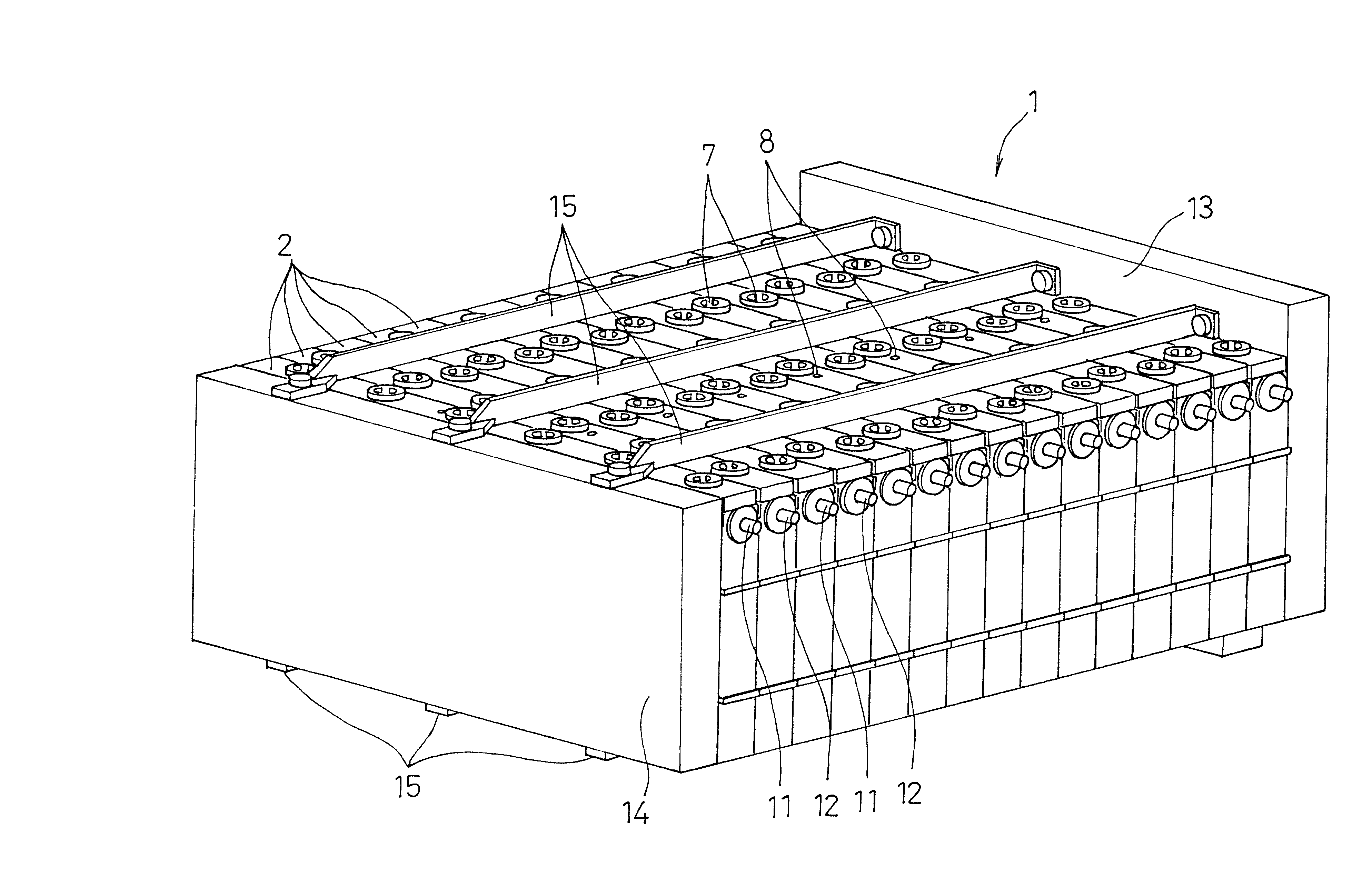
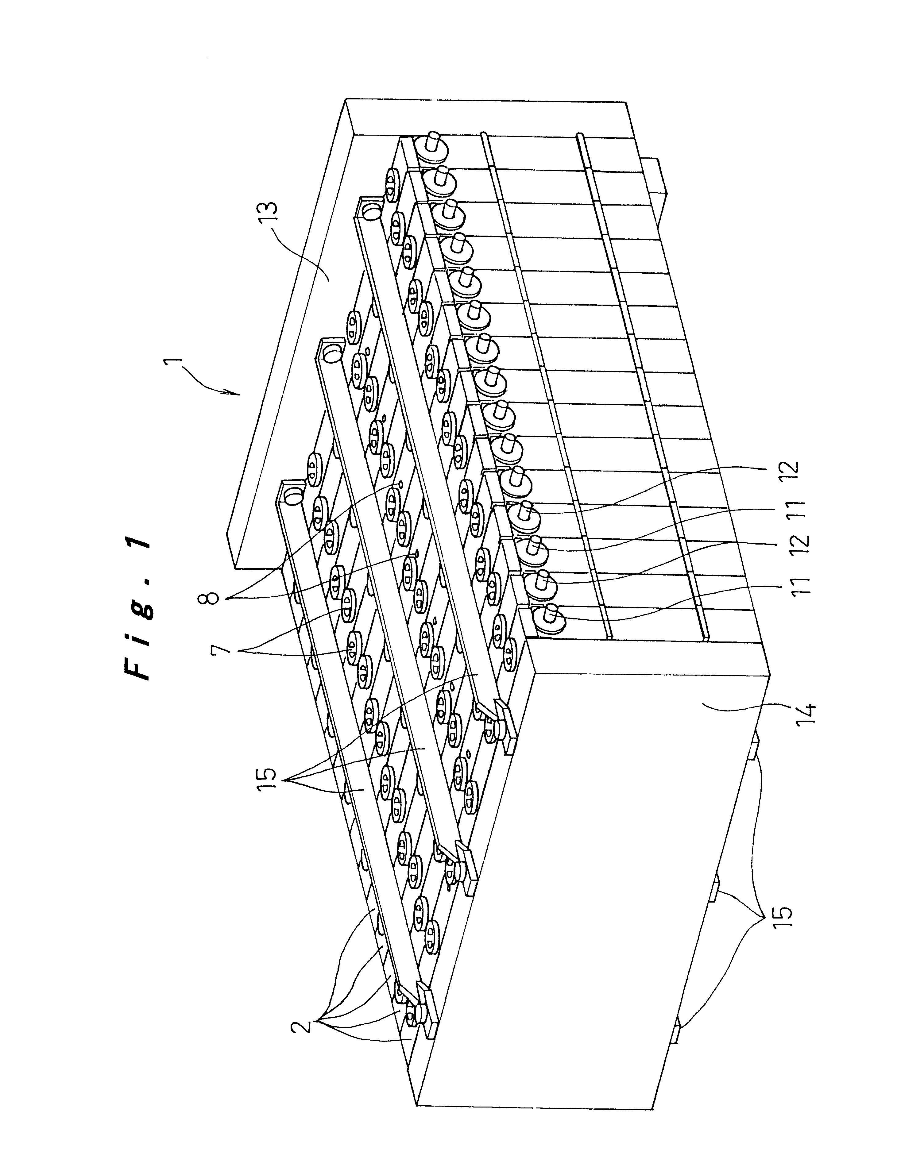
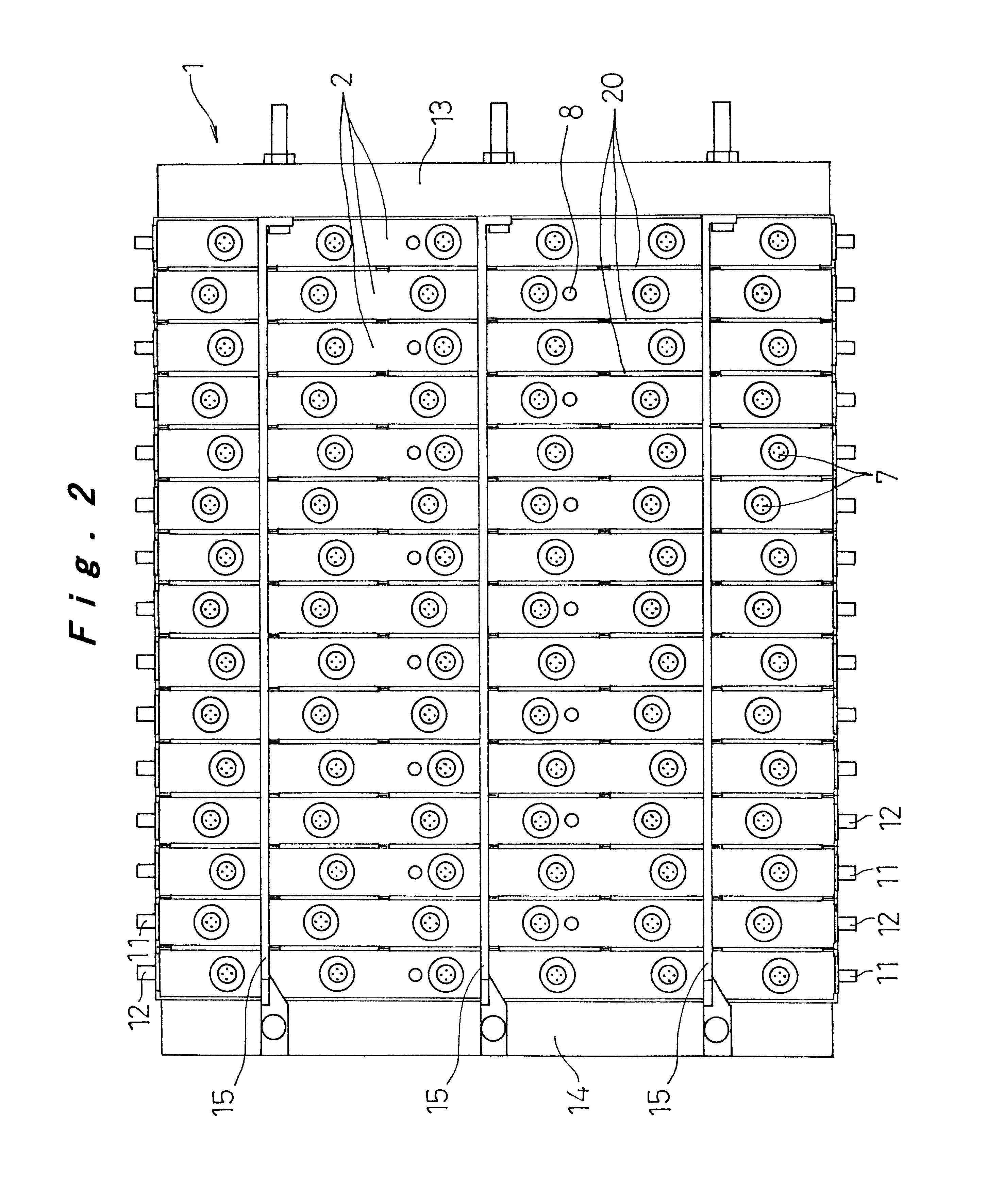
One embodiment of a battery pack according to the present invention is described below with reference to FIG. 1 to FIG. 6.

In FIG. 1 and FIG. 2, a battery pack 1 according to this embodiment is constituted such that it can conveniently be employed as the drive power source for an electric vehicle and is constituted by arranging adjacent each other a plurality (in the example illustrated, 15) of prismatic battery modules 2 of flat plate shape comprising nickel metal hydride batteries. Positive electrode and negative electrode connecting terminals 11, 12 project at the upper ends of both end faces in the direction of elongation of battery modules 2, the positive electrode and negative electrode connecting terminals 11, 12 of battery modules 2 being adjacently arranged so as to be alternately in opposite directions; thus, battery modules 2 are connected in series by sequential mutual connection of adjacent connecting terminals 11, 12. The battery pack 1 is constituted as a unitized body...


PUM

PropertyMeasurementUnit
output poweraaaaaaaaaa
electromotive forceaaaaaaaaaa
internal pressureaaaaaaaaaa

Abstract

A battery module is constructed of an integral battery case which is constituted by forming a plurality of prismatic cell cases into a unitized body, wherein positive electrode plates and negative electrode plates laminated alternately upon one another with intervening separators are respectively accommodated in each of the cell cases, thereby constituting a plurality of cells, these cells being electrically connected in series. A plurality of such battery modules are arranged in a direction in which the electrode plates within each cell are laminated in a condition with coolant passages formed between the battery modules, and bound tightly together with end plates arranged at both ends in the direction of adjacent arrangement of the battery modules.

Description

1. Technical Field of the InventionThe present invention relates to a battery pack constructed with a plurality of battery modules that are respectively constituted by unitizing a plurality of cells.2. Description of Related ArtIt has been the practice to constitute a battery pack, in order to achieve a necessary output power, when employing rechargeable batteries. In a battery pack, generally, a plurality of battery modules, each being constituted by connecting a plurality of cells in series and bonding them into a unitized body, are arranged in parallel and mutually connected in series.FIG. 11 shows a conventional battery module made by connecting a plurality of cells and coupling them together as one. In this battery module, a plurality of cells 41 (41a to 41j) are arranged side by side, with the long lateral walls of their cell cases opposite each other. End plates 52 are arranged against the outside of the cells 41a and 41j at both ends, and the group of cells and the two end p...

Claims


Application Information

Patent Timeline
Patent Type & Authority Patents(United States)
IPC IPC(8): H01M2/10H01M2/02H01M10/28H01M10/04H01M10/24H01M10/42H01M10/50H01M50/528H01M10/60H01M10/613H01M10/625H01M10/647H01M10/653H01M10/6551H01M10/6557H01M10/6563H01M10/6566H01M10/6568H01M50/103H01M50/209H01M50/291H01M50/529
CPCH01M2/0237H01M2/0245H01M2/1077H01M10/0413H01M10/281H01M10/5004H01M10/5032H01M10/5059H01M10/5067H01M10/5073H01M10/5075H01M2/024Y02E60/124H01M10/5008H01M10/5016H01M10/5055H01M10/625H01M10/6563H01M10/647H01M10/6557H01M10/6567H01M10/6555H01M10/617H01M10/6566H01M10/613Y02E60/10H01M50/258Y02P70/50H01M50/209H01M50/103H01M50/291
Inventor KIMURA, TADAOHAMADA, SHINJIOGATA, YOSHIAKIYAMAUCHI, TOMOKAZUSEKIMORI, TOSHIYUKI
Owner PANASONIC CORP
Learn More