Ventilation seat

a technology of ventilating seat and seat body, which is applied in the field of ventilating system, can solve the problems of affecting the temperature of the seat, affecting the comfort of the seat, and causing further discomfort, and achieves the effect of simple design

Inactive Publication Date: 2003-06-17
LEAR CORP
View PDF7 Cites 99 Cited by
  • Summary
  • Abstract
  • Description
  • Claims
  • Application Information

AI Technical Summary

Benefits of technology

Therefore, it is an object of the invention to provide a ventilation system for a car seat, said system obviating the above-mentioned problems and having a simple design, at the same time as the system does not have a detrimental effect on the driver's / passenger's health.
Preferably, said network of ducts comprises ducts extending substantially in the planar direction of the seat part as well as substantially in the thickness direction of the seat part, which permits a satisfactory removal of heat (ducts in the thickness direction) and moisture (ducts in the planar direction).
Said network of ducts further comprises an additional number of joint ducts which extend substantially in the thickness direction of the seat part and which constitute said at least partially closable ducts. These joint ducts end at the sitting surface of the seat, and the orifices of these joint ducts can be spread over the sitting surface in such manner that a satisfactory and quick cooling is provided. Moreover, the partially closable joint ducts are connected, in their ends facing away from the sitting surface of the seat part, with at least one of said branch ducts via connection ducts extending substantially in the planar direction. As a result, air can be conveyed from the upper side of the seat, via branch ducts and the closable joint ducts, to be gathered in the branch ducts for a common discharge of all air through the same.
Suitably, a fan element is also arranged in fluid contact with said branch ducts on the side of the seat part opposite to the sitting surface of the seat part. This fan element is suitably of a one-way type and exhausts air from the sitting surface of the seat part through said network of ducts and to the opposite side of the seat part. This arrangement permits an efficient flow of air through the network of ducts and provides cooling over a large surface of the seat by means of only one fan element thanks to the above-mentioned distribution of the orifices of the joint ducts over the sitting surface.
The above-mentioned objects are also achieved by a method for comfort ventilation comprising the steps of starting by remote control a fan element which is arranged in connection with the seat part, generating by means of said fan element (6) a flow of air through a network of ducts (2, 3, 4, 5) which is arranged in the seat part and whose orifices are distributed over the sitting surface, and closing at least partially a subset of said ducts, and thus redirecting the air flow through the seat part when applying a load to the seat part. Thus, this method makes it possible to pre-cool the seat part before the driver / passenger sits down in the vehicle, after which a change takes place from a cooling phase to a moisture-removing phase the moment the driver / passenger sits down in the vehicle.
Suitably, the step of completely or partially closing certain ducts is carried out by compressing the seat part when applying a load, thereby causing mechanical changes in the structure of the seat bottom. Preferably, the step of at least partially closing a subset of ducts is carried out by compressing connection ducts arranged in the seat part when applying a load. This is a purely mechanical and very simple structure, which eliminates the need of sensors and the like for this purpose. In addition, it is ensured that the transition between the various phases takes place the moment the driver / passenger first applies a load to the seat part.

Problems solved by technology

Special problems arise in a warm and sunny climate, as the interior of a parked vehicle can reach very high temperatures.
It goes without saying that this affects the temperature of the car seats, which can get very hot, in particular if the covering is dark.
As a consequence, a person entering the vehicle may burn himself when sitting down on the vehicle seat.
Moreover, there is further discomfort at an initial stage, since the driver is probably perspiring after having been outside in the hot climate.
At the same time, the draught must not be too strong as this may have a detrimental effect on the driver's / the passenger's health.
This is a very expensive solution, which is sensitive to strain, in particular due to the control electronics which has to be integrated in the seat bottom to control the fans.
Other solutions comprise a number of sensors and the like in the seat bottom to control the power of the fans and the like, but these systems also require electronics integrated in the seat bottom and are thus sensitive.

Method used


Image

  • Ventilation seat
  • Ventilation seat
  • Ventilation seat

Examples


Embodiment Construction

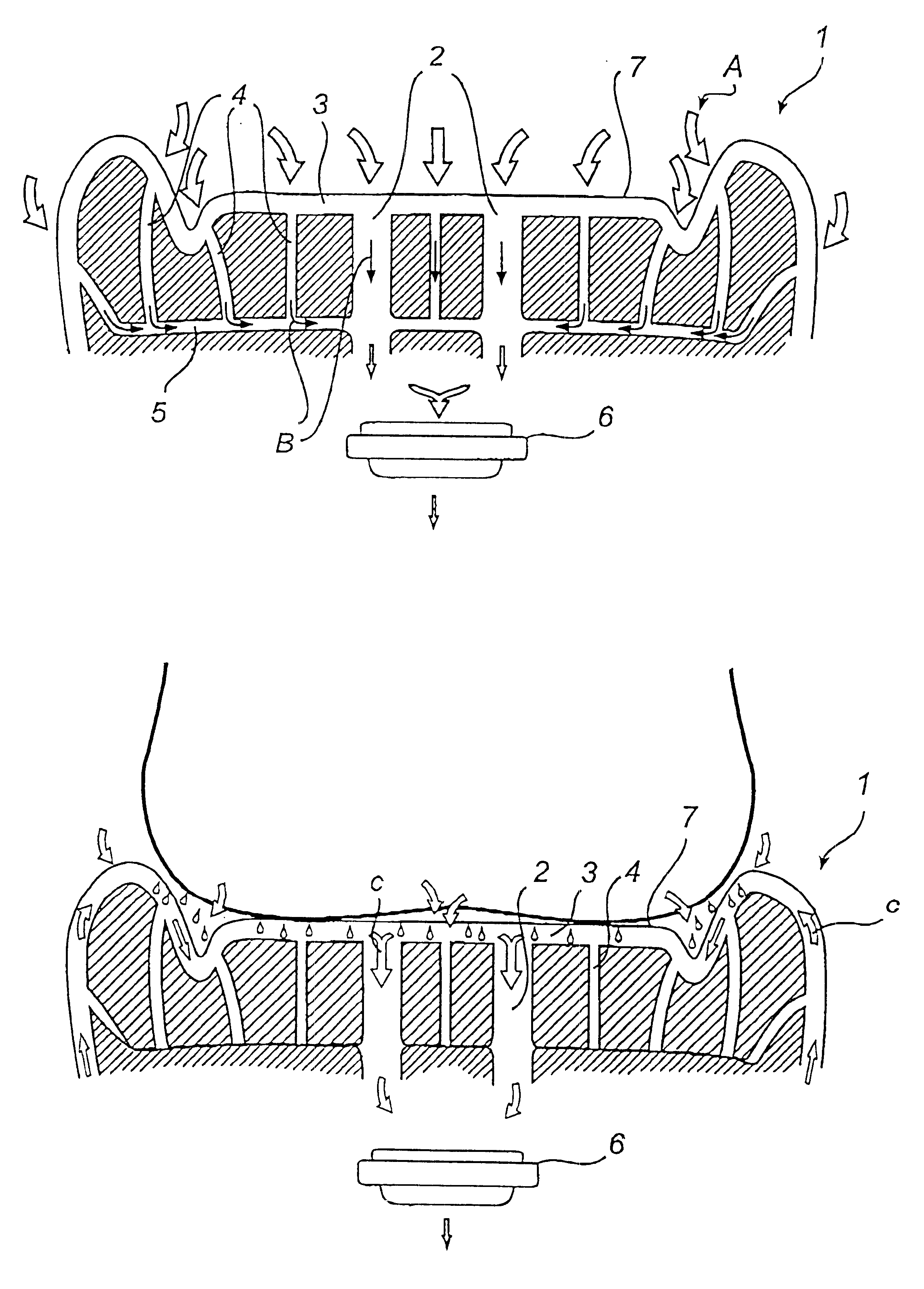
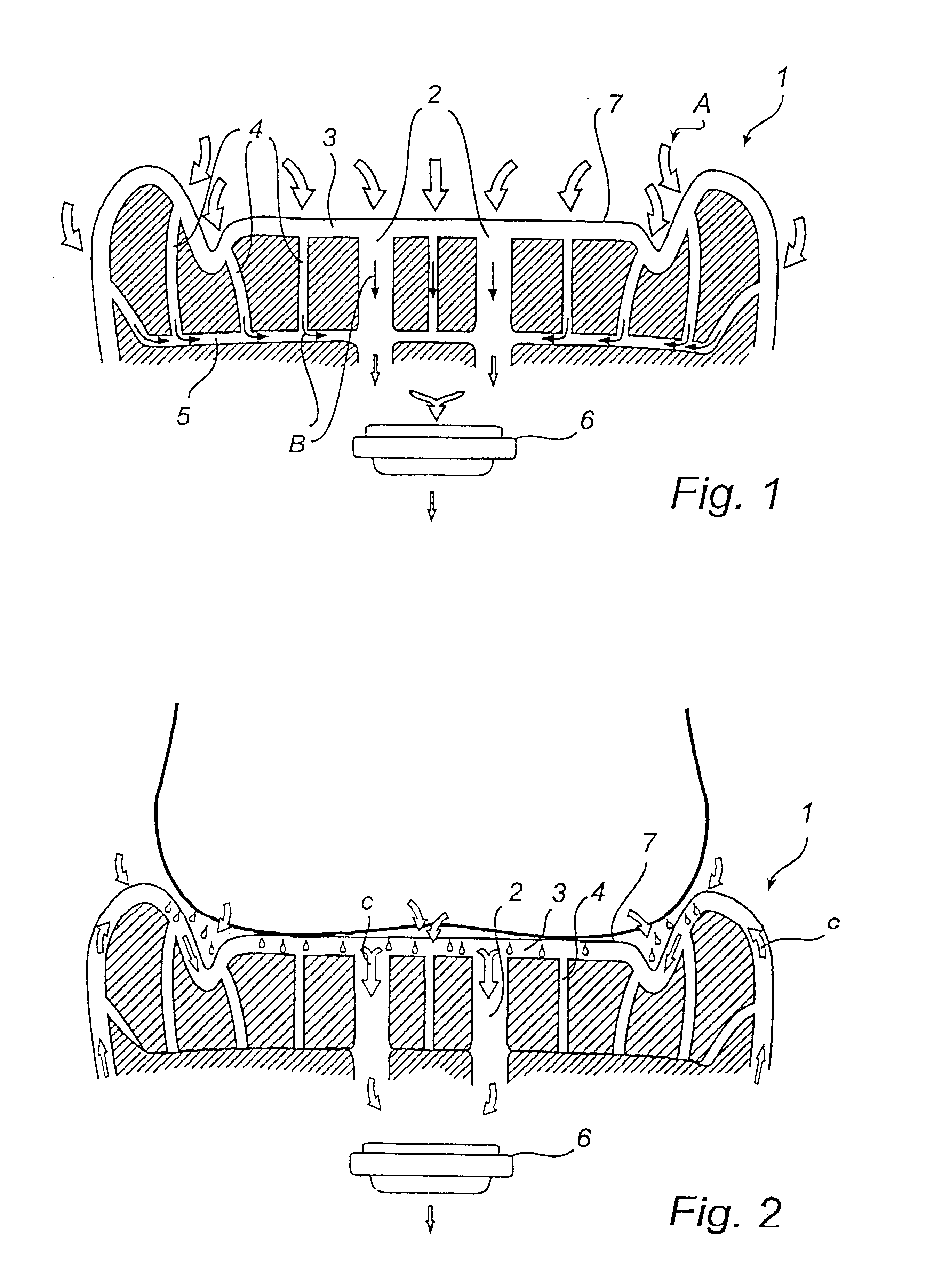
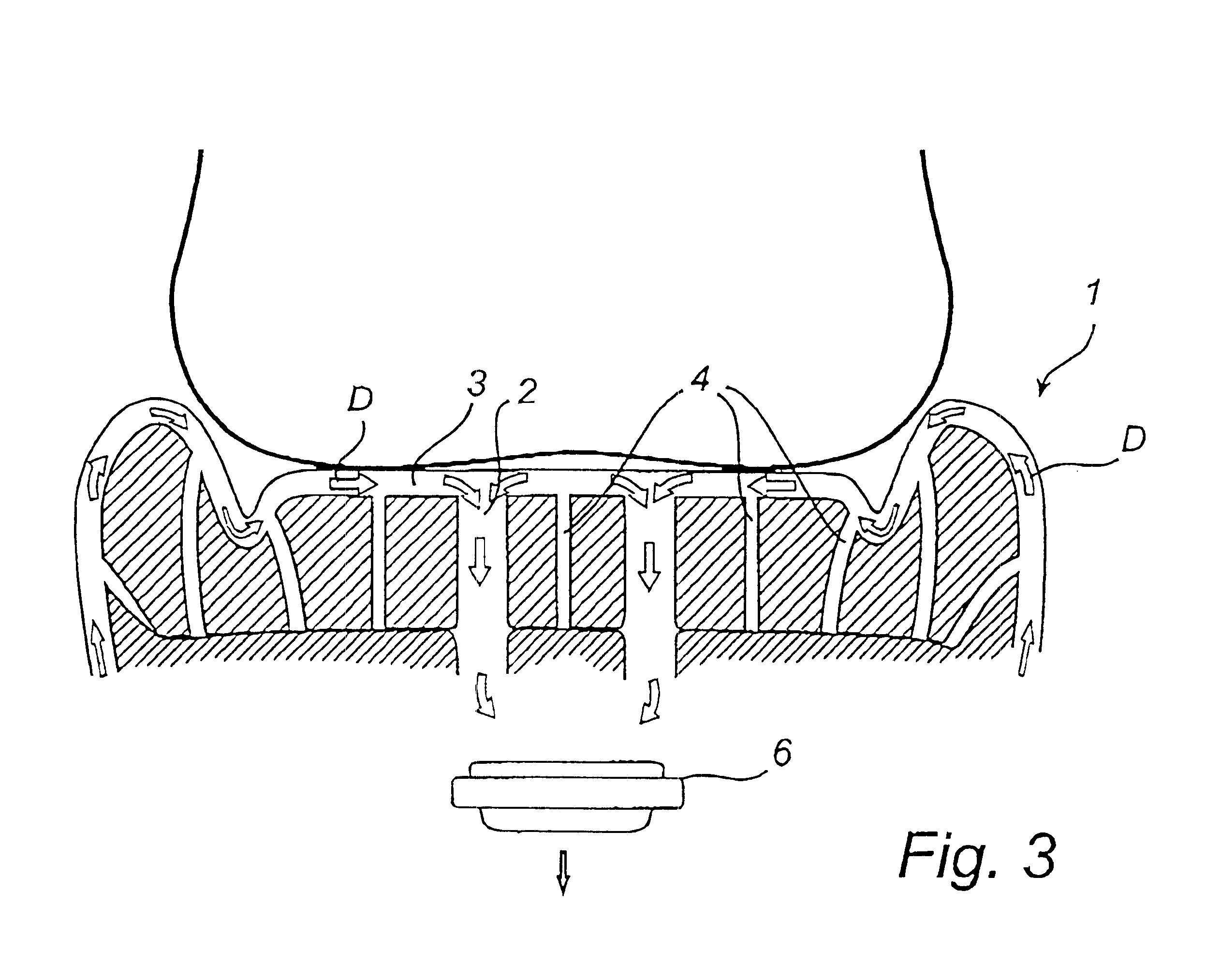
FIGS. 1, 2 and 3 show a part of a car seat in cross-section. In these Figures, the seat part is a seat bottom 1, but the invention could just as well be applied to the backrest of the seat. The seat bottom has a network of ducts 2, 3, 4, 5, which cross the seat bottom 1 in a number of different directions. In this embodiment, there is a number (two are shown) of branch ducts 2, which are located in the middle portion of the seat bottom. These branch ducts 2 have a comparatively large diameter and cross substantially the entire seat bottom 1 in its thickness direction. In direct connection with these branch ducts, on the underside of the seat bottom, a fan is arranged, which can exhaust air through the seat bottom, preferably from the upper side of the seat bottom to its underside. The surface of the seat bottom is covered by a permeable layer 7. This layer should be permeable to both moisture and air and can, for instance, be a layer of textile, perforated leather or the like. Along...


PUM


Abstract

A vehicle seat having a ventilation system includes a network of ducts within the seat bottom, and a fan for moving air away from the seat surface. The ventilation system is configured such that a single fan may selectively move air through some or all of the ducts. Before a vehicle occupant sits in a seat, air is moved through all of the ducts to reduce the temperature at the seat surface. When the occupant sits in the seat, certain ducts in the network are closed to air flow. The air flow is now limited to the remaining ducts, which allows for efficient removal of moisture from the seat surface. After the temperature and moisture at the seat surface have reached desired levels, the speed of the fan is reduced to ensure that the occupant does not experience an unpleasant draught.

Description

The present invention relates to a vehicle seat having two seat parts, namely a seat bottom and a backrest, at least one of the seat parts comprising a ventilation system. The invention further relates to a method for comfort ventilation of a vehicle seat.In the automotive industry, sitting comfort and driving comfort is an important field. Special problems arise in a warm and sunny climate, as the interior of a parked vehicle can reach very high temperatures. It goes without saying that this affects the temperature of the car seats, which can get very hot, in particular if the covering is dark. As a consequence, a person entering the vehicle may burn himself when sitting down on the vehicle seat. Moreover, there is further discomfort at an initial stage, since the driver is probably perspiring after having been outside in the hot climate. Thus, it is important to lead away the moisture from the surface of the seat. At the same time, the draught must not be too strong as this may ha...

Claims


Application Information

Patent Timeline
Patent Type & Authority Patents(United States)
IPC IPC(8): A47C7/72A47C7/74B60N2/56
CPCA47C7/74B60N2/5635B60N2/56B60N2/565
Inventor ANDERSSON, CHRISTERANDREASSON, BENGTERIKSSON, HARRY
Owner LEAR CORP
Why Eureka
Try Eureka