Wing plow assembly

a technology of wing plows and assembly parts, which is applied in the direction of snow cleaning, way cleaning, construction, etc., can solve the problems of actuation arrangements, compounded difficulties in using wing plows, and limited versatility of most wing plow mounts

Inactive Publication Date: 2003-06-24
BURKE TRUCK & EQUIP
View PDF27 Cites 38 Cited by
  • Summary
  • Abstract
  • Description
  • Claims
  • Application Information

AI Technical Summary

Problems solved by technology

Difficulties in using wing plows are compounded because plowing generally occurs in conditions of low visibility (generally early in the morning during or shortly after a snowstorm), and at high speed owing to the need to rapidly enhance road safety for other motorists.
These difficulties are compounded by the limited versatility of most wing plow mounts and actuation arrangements.
As a result, multiple passes with the plowing vehicle may be required to adequately remove snow from some areas.
Additionally, it is generally impossible or very difficult for an operator to adjust the height of a wing plow to clear a raised area, e.g., above a curb, and when this is done the effective length (reach) of the wing plow tends to be greatly decreased.
Wing plows are also subject to greater durability and maintenance concerns than front moldboards.
Like front moldboards, wing plows experience significant wear and shock as they scrape along an irregular roadway surface, and as they experience loading from snow, ice, and impact with objects in and alongside the roadway.
However, since wing plows have their primary connection to the plowing vehicle at their sides, rather than at their centers (as with front moldboards), this connection is subject to significant stress owing to the moment forces generated during plowing.
While these measures strengthen the support for the wing plow, they can lead to greater maintenance burdens in the long run.
When the wing plow's primary connection to the plowing vehicle (at the side of the moldboard) is reinforced, this often tends to add such bulk to the wing plow mounting arrangement that access to the plowing vehicle's hood is severely obstructed.
This causes difficulties because the vehicle's hood needs to be lifted quite often during the plowing season for maintenance of the vehicle's engine, the plowing controls and hydraulics, etc., and if the plow frame and / or other wing plow mounting structure requires removal every time the vehicle hood is to be accessed, this can diminish the plowing vehicle's available operating time.
Access to the hood and / or other components of the plowing vehicle can be further obstructed when supports are added between the plowing vehicle and the outer end of the wing plow, and such supports, being subject to significant stress and wear, require additional maintenance.
This is particularly true if such supports include hydraulics or similar "controllable" components which are relatively complex and which are more susceptible to shock damage, and which also enhance the operational complexity of the wing plow owing to the plowing vehicle operator's need to actuate these components, along with other components of the plow, during plowing operations.

Method used


Image

  • Wing plow assembly
  • Wing plow assembly
  • Wing plow assembly

Examples


Embodiment Construction

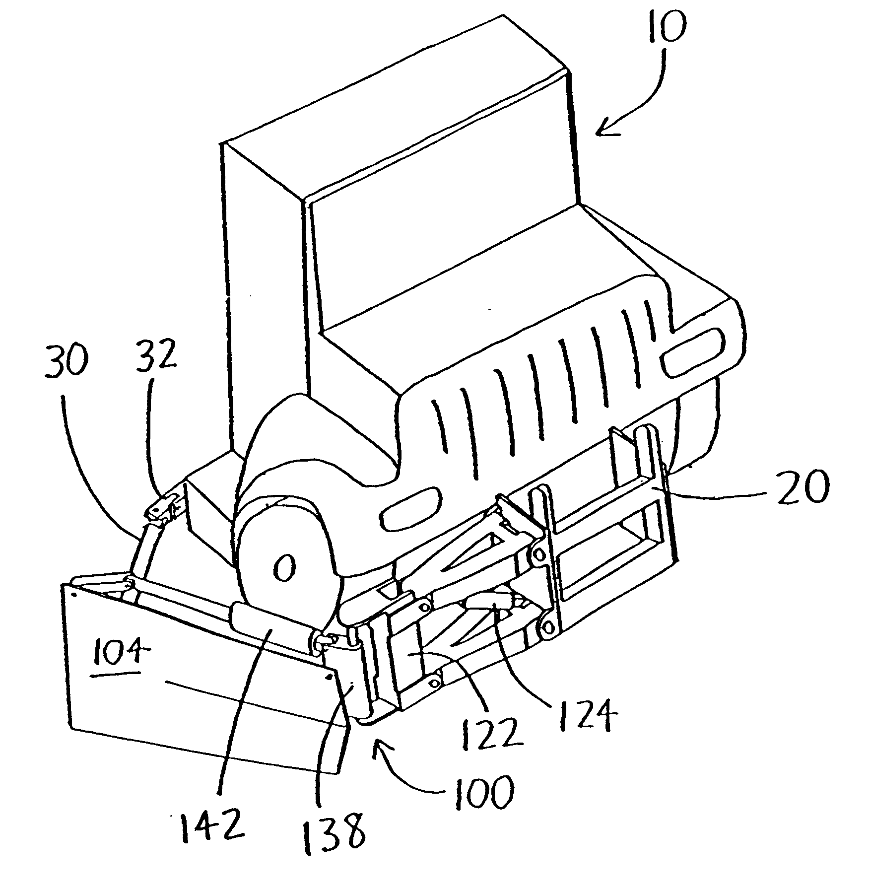
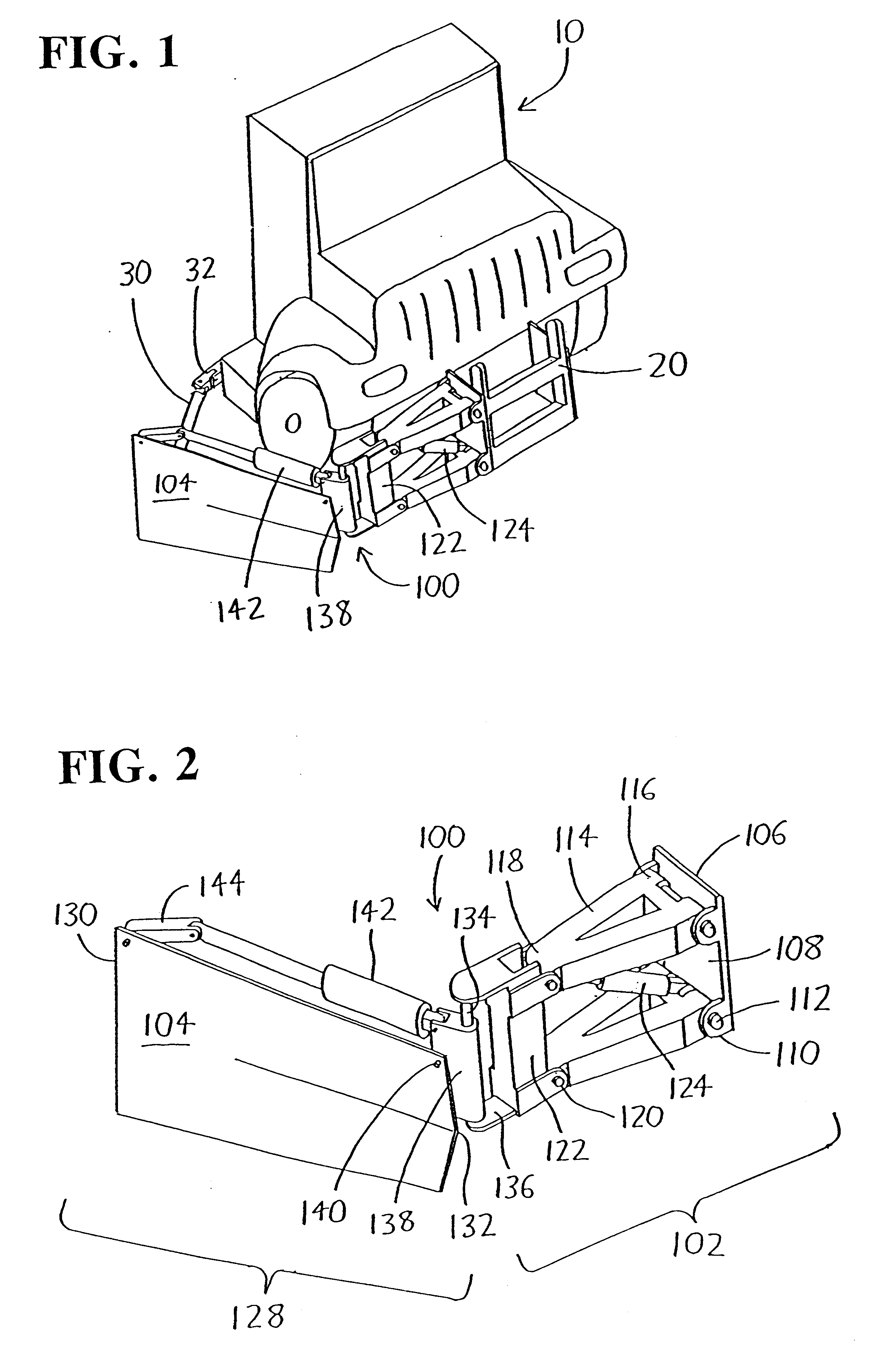
Referring to FIG. 1, the front portion of a plowing vehicle 10 is shown with a front moldboard frame 20 provided at the middle of the front of the vehicle 10. The moldboard frame 20 may be affixed to a front moldboard and / or to the moldboard's reversing table (i.e., the pivoting arrangement allowing "steering" of the front moldboard), but these components are not illustrated in FIG. 1. It should be understood that the moldboard frame 20 illustrated in FIG. 1 merely has an exemplary configuration, and that moldboard frames compatible with the invention (the wing plow assembly and the various subassemblies and components thereof) may take a variety of forms other than the one shown. An exemplary version of the invention, which is overall depicted at 100 throughout the figures, will now be discussed in detail.

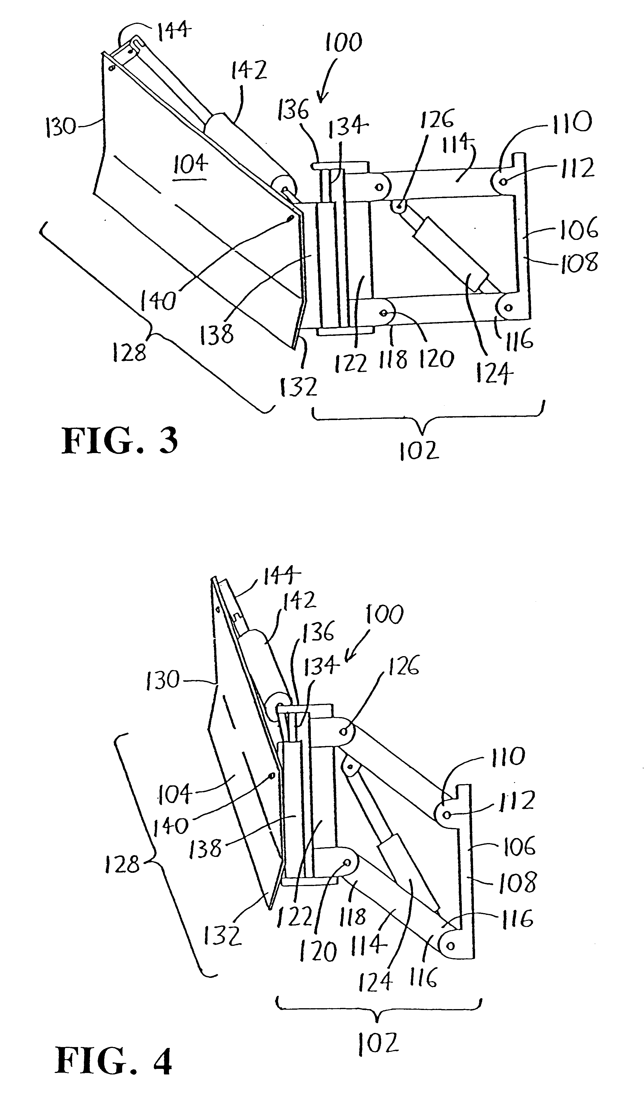
The wing plow assembly 100 initially includes a lift subassembly 102 which enables vertical lifting of wing plow 104. The lift subassembly 102 includes a base member 106 which is ...


PUM


Abstract

A wing plow assembly includes a base member for mounting to a plowing vehicle (or to structures connected to a plowing vehicle, such as on a plow frame for a front moldboard). Upper and lower height adjustment arms each have a base end pivotally anchored to the base member, and an opposing plow end pivotally linked to a plow positioning leg. The base member, height adjustment arms, and plow positioning leg form a parallelogram linkage wherein the plow positioning leg may vertically swing on the height adjustment arms about the base member. A wing plow having a length extending between a inner end and a outer end has its inner end affixed to the plow positioning leg so that the wing plow may also vertically swing about the base member, thereby allowing the wing plow to be raised and lowered with respect to the base member (and thus with respect to the plowing vehicle). Additionally, the wing plow inner end is preferably affixed to the plow positioning leg so that it may swing horizontally thereon, thereby allowing the wing plow outer end to be folded toward or away from the plowing vehicle. The wing plow inner end is affixed to the plow positioning leg (or associated structure), and a wing fold linear actuator then extends from the outer end of the wing plow to affix to the plow positioning leg (or associated structure). The wing fold linear actuator is extendible and contractible to horizontally swing the wing plow about the plow positioning leg, and thus fold the wing plow with respect to the plowing vehicle.

Description

This disclosure concerns an invention relating generally to snowplows, and more specifically to wing plows (also known as patrol wings) for snowplows.Snowplows such as those commonly used to plow snow from roadways, parking lots, and other areas often include a front blade (often referred to as a front moldboard or similar terms) and a side blade (often referred to as a wing plow, wing blade, patrol wing, or similar terms). The front and side blades are often provided on a removable plow frame provided at the front of the plowing vehicle, and which may be detached from the plowing vehicle during snow-free months to allow other uses for the vehicle.Regarding the side blades (which will generally be referred to herein as "wing plows"), these generally have one of their sides hingedly mounted to the front of the plowing vehicle, and are driven by linear actuators such as hydraulic cylinders so that a wing plow may be folded up alongside (and somewhat parallel to) the plowing vehicle wh...

Claims


Application Information

Patent Timeline
Patent Type & Authority Patents(United States)
IPC IPC(8): E01H5/06E01H5/04
CPCE01H5/067
Inventor JONES, JAYSON D.JONES, DANIEL K.
Owner BURKE TRUCK & EQUIP
Why Eureka
Try Eureka