Thrombectomy catheter deployment system

a thrombosis catheter and deployment system technology, applied in the field of thrombosis catheter deployment system, can solve the problems of difficult use, limited tolerance of current thrombosis catheter utilization devices for nonsequential setup steps, and difficulty in thrombosis during interventional procedures, etc., to achieve economic benefits, high tolerance, and adequate integrity

Active Publication Date: 2007-03-29
BOSTON SCI LTD
View PDF24 Cites 78 Cited by
  • Summary
  • Abstract
  • Description
  • Claims
  • Application Information

AI Technical Summary

Benefits of technology

[0045] The thrombectomy catheter deployment system employs an insert molded pump. Insert molding the pump enables the pump to be made economically, while still maintaining adequate integrity. Molding the plastic and glass-filled nylon about a stainless steel insert enables the high tolerance fits to be created by the molding process rather than have high tolerance fits machined into the stainless steel parts. Insert molding the pump also reduces the weight of the pump, making the packaging easier, as generally packaging robustness needs to increase with increased weight of the packaged item. Finally, insert molding enables the elimination of several of the components, thus further reducing cost and complexity.
[0046] The thrombectomy catheter deployment system contains a barcode reader for automatic mode selection and for pertinent data regarding the individual catheter tube and individual pump and associated operating parameters. The need for service to upgrade the software on the drive unit for new catheter modes is eliminated as the information can be contained on the barcode. Also eliminated is the need for the customer to input the mode information. The barcode information is protected by a data protection scheme, computer redundancy check (CRC), that ensures that the mode information is input into the drive unit in a reliable fashion. Furthermore, a special alphanumeric sequence, or encryption technique, can be built into the barcode information to ensure that only authorized proprietary catheters and pumps are used in the thrombectomy catheter deployment system. Note that the barcode and the barcode reader may, in fact, be a radio-frequency transponder and reader or other equivalent digital tagging technology.
[0047] A bag spike and associated components are included which minimize bubble formation for use with a bubble trap. The bag spike is designed to prevent a continuous stream of bubbles from entering the pump. The bag spike uses a high flow spike, as well as larger inside diameter tubing, to reduce the fluid restriction between the bag and the pump. Furthermore, the bubble trap is positioned at the pump inlet. The bubble trap is designed with interior walls to enhance debubbling of the saline prior to the pump inlet. Therefore, if the bag spike or saline supply tube is perforated, any bubbles that enter the tube will be removed by the bubble trap. If the bubble trap itself were to develop a perforation, the saline would leak out rather than suck air into the trap since it is attached directly at the pump inlet and has sufficiently low fluid restriction.

Problems solved by technology

Current thrombectomy catheter utilization devices include a nondisposable drive unit which accommodates disposable components such as a catheter, a pump, a waste bag, bubble traps, a bag spike, and other closely associated components which are loaded into or closely associated with the drive unit support structures which are used to operate a thrombectomy catheter where the use of such is characterized by customers as a relatively difficult to use system.
The discovery of thrombus during an interventional procedure is often an unexpected and emergency situation.
Although a well trained individual can set up a thrombectomy catheter utilization device in less than a minute, current thrombectomy catheter utilization devices have limited tolerance for nonsequential setup steps.
Without the combination of the pump / catheter assembly, operation would be extremely difficult.

Method used


Image

  • Thrombectomy catheter deployment system
  • Thrombectomy catheter deployment system
  • Thrombectomy catheter deployment system

Examples


Embodiment Construction

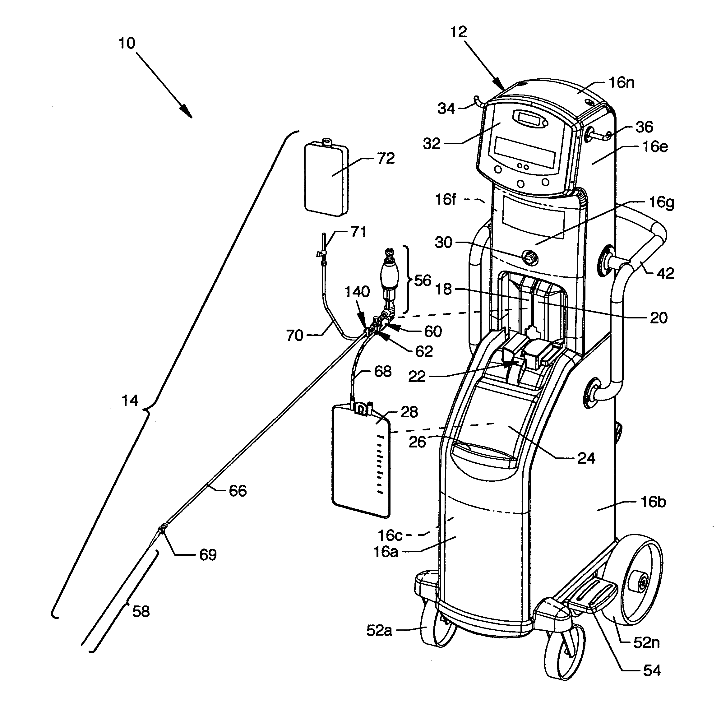
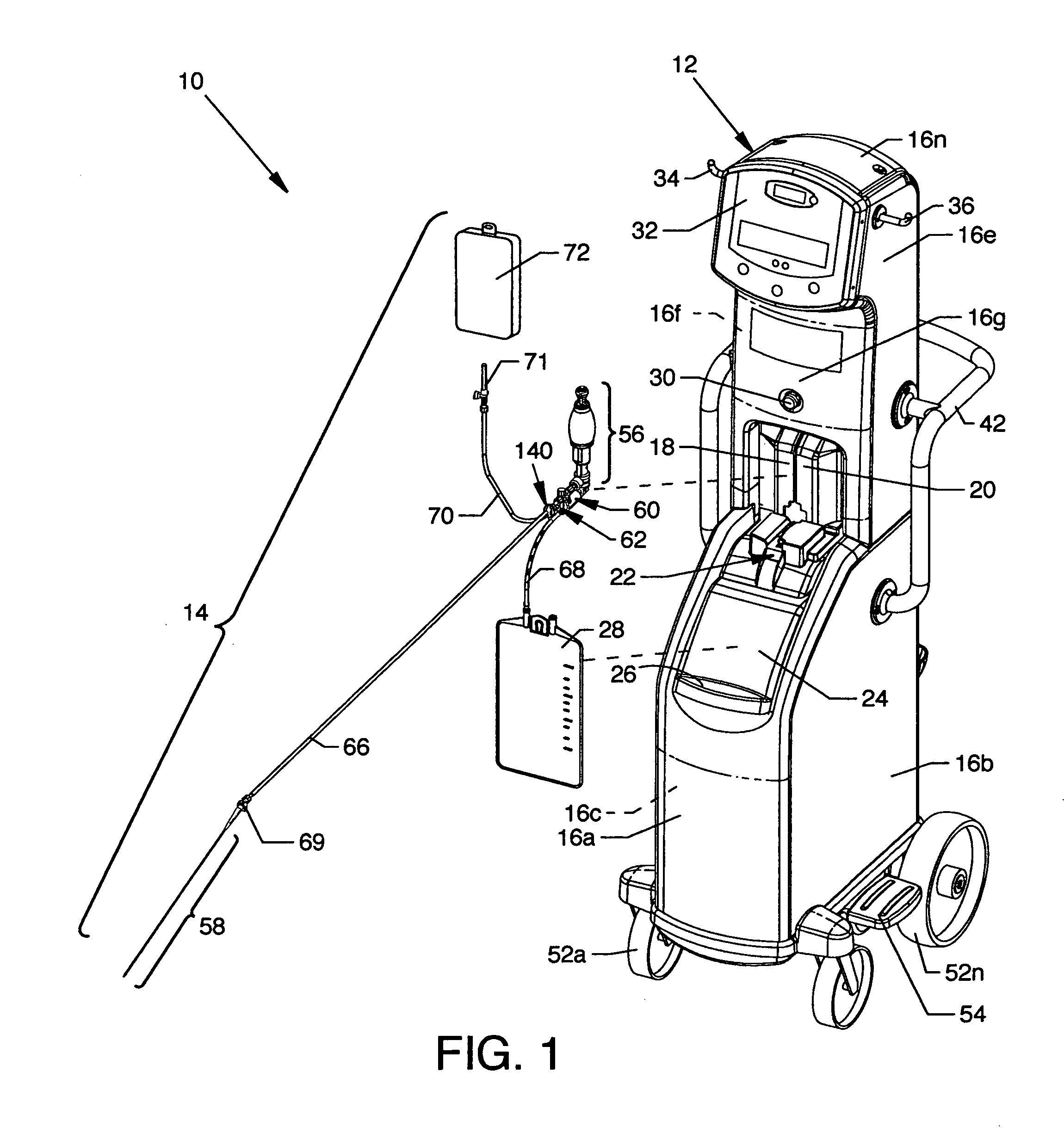
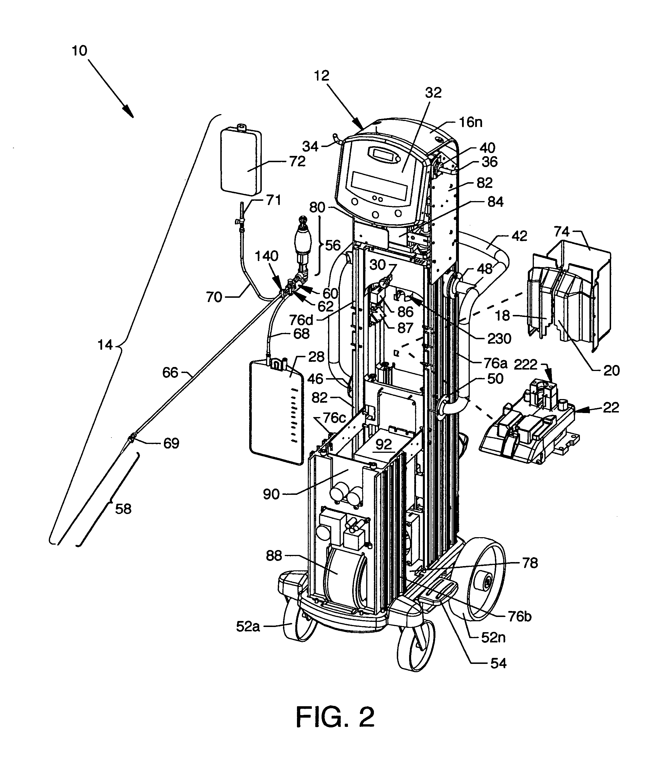
[0093]FIG. 1 is a view of a thrombectomy catheter deployment system 10, the present invention. Directly visible in the illustration are a drive unit 12 and a pump / catheter assembly 14 comprising the thrombectomy catheter deployment system 10. Shown on the drive unit 12 are a plurality of removable panels 16a-16n about and along the drive unit 12 enclosing structure exposed to view in FIG. 2. Centrally located in the drive unit 12 and aligned to the lower region of the panel 16g are automatically opening doors 18 and 20 which open to expose the interior of the drive unit 12 and the rear portion of a carriage assembly 22 also shown in FIG. 2. The front portion of the carriage assembly 22, which accommodates the pump / catheter assembly 14, is shown extending from the interior of the drive unit 12 beneath the closed doors 18 and 20. The carriage assembly 22 is rearwardly and forwardly positionable to the closed and open positions, respectively. A removable drip tray 24 is shown in obliqu...


PUM


Abstract

A thrombectomy catheter deployment system which greatly simplifies setup procedures and operation of a thrombectomy catheter includes a stand alone drive unit and a disposable pump/catheter assembly which is manually placed into a carriage assembly in the drive unit. The pump/catheter assembly has a plurality of preconnected components including tubular structure and a thrombectomy catheter connected thereto and is transported into or out of the interior of the drive unit for automatic high pressure pump piston head engagement or disengagement with a reciprocating linear actuator and for automatic engagement or disengagement of an effluent waste tube with a roller pump. A barcode reader senses specific operational data pertaining to an individual pump and provides an interface for operation of the reciprocating linear actuator. A bubble trap incorporated for effective debubbling of saline solution is closely coupled to an insert molded pump having an improved valve arrangement. A spiked bag with large tubing is incorporated for bubble-free transfer of saline.

Description

CROSS REFERENCES TO RELATED APPLICATIONS [0001] None. BACKGROUND OF THE INVENTION [0002] 1. Field of the Invention [0003] In the human body blockages in blood vessels, arteries and the like often oppose the free flow of blood therein, one such blockage of which is thrombus. Thrombus is coagulated blood that is developed invivo. Thrombus blocks blood flow to living tissue leading to ischemia and eventually tissue death. Depending on the end organ and the amount of blocked blood flow, the effects of thrombus can range from unnoticeable to patient death. Thrombus residing in a variety of native vessels and grafts can be treated. The occurrence and presence of thrombus occurs in several ways. First, it occurs in coronary procedures where thrombus is associated with myocardial infarction or heart attack. Thrombus is also common in older saphenous vein bypass grafts. Second, peripheral artery interventional procedures can encounter thrombus as well. The use of synthetic grafts and stents ...

Claims


Application Information

Patent Timeline
Patent Type & Authority Applications(United States)
IPC IPC(8): A61M1/00
CPCA61B19/0248A61B2019/025A61M5/14232A61B17/22A61M25/0122A61M2205/6018A61M5/36A61B50/10A61B50/13A61B17/32037A61M5/14216
Inventor THOR, ERIC JOELBONNETTE, MICHAEL JOHNAASEN, NICOLE JAYEABBOTT, MARTYN STUARTBALL, DOUGLAS JAMESCROLL, WALTER CHARLESCUMMINGS, DAVID CHARLESGRANT, CHAD NICHOLASHILSE, MARK ALFREDKARPINSKI, JAMES FREDRICKKNEIP, DANIEL JOSEPHROGERS, JEFFREY WILLIAMSCHERGER, ERNEST RALPH IIITESCHENDORF, JOHN LLOYDWEISEL, STEPHEN EARLWEST, DAVID WOODRUFF
Owner BOSTON SCI LTD
Why Eureka
Try Eureka