Method for determining the air aspirated by an internal combustion engine, and sensor for an internal combustion engine

a technology of internal combustion engine and air aspiration sensor, which is applied in the direction of machines/engines, electric control, instruments, etc., can solve the problems of inability to accurately determine the air aspiration rate, the air flow rate meter is wrong, and the variable that affects the air flow rate is ignored

Inactive Publication Date: 2003-06-24
VOLKSWAGEN AG
View PDF6 Cites 45 Cited by
  • Summary
  • Abstract
  • Description
  • Claims
  • Application Information

AI Technical Summary

Problems solved by technology

One problem in such known methods for determining the air aspirated by an internal combustion engine is that in determining the air flow rate, variables that effect the air flow rate are ignored.
If the ambient air is very humid, the humidity makes the air flow rate detected by the air flow rate meter wrong, because not only the air that can be combusted in the engine but at the same time water vapor that cannot be combusted is detected and thus leads to very disadvantageous changes in emissions values.

Method used


Image

  • Method for determining the air aspirated by an internal combustion engine, and sensor for an internal combustion engine
  • Method for determining the air aspirated by an internal combustion engine, and sensor for an internal combustion engine
  • Method for determining the air aspirated by an internal combustion engine, and sensor for an internal combustion engine

Examples


Embodiment Construction

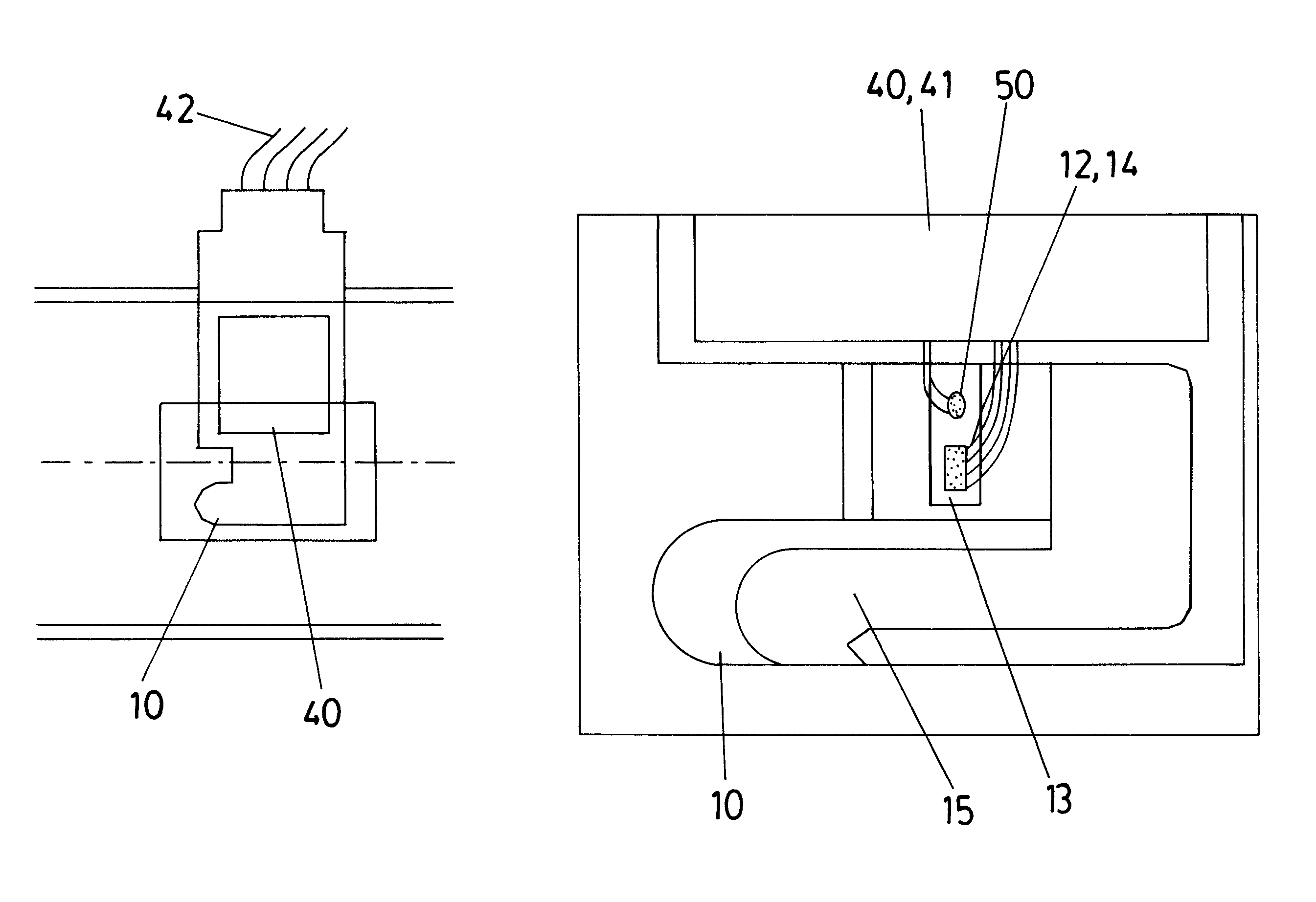
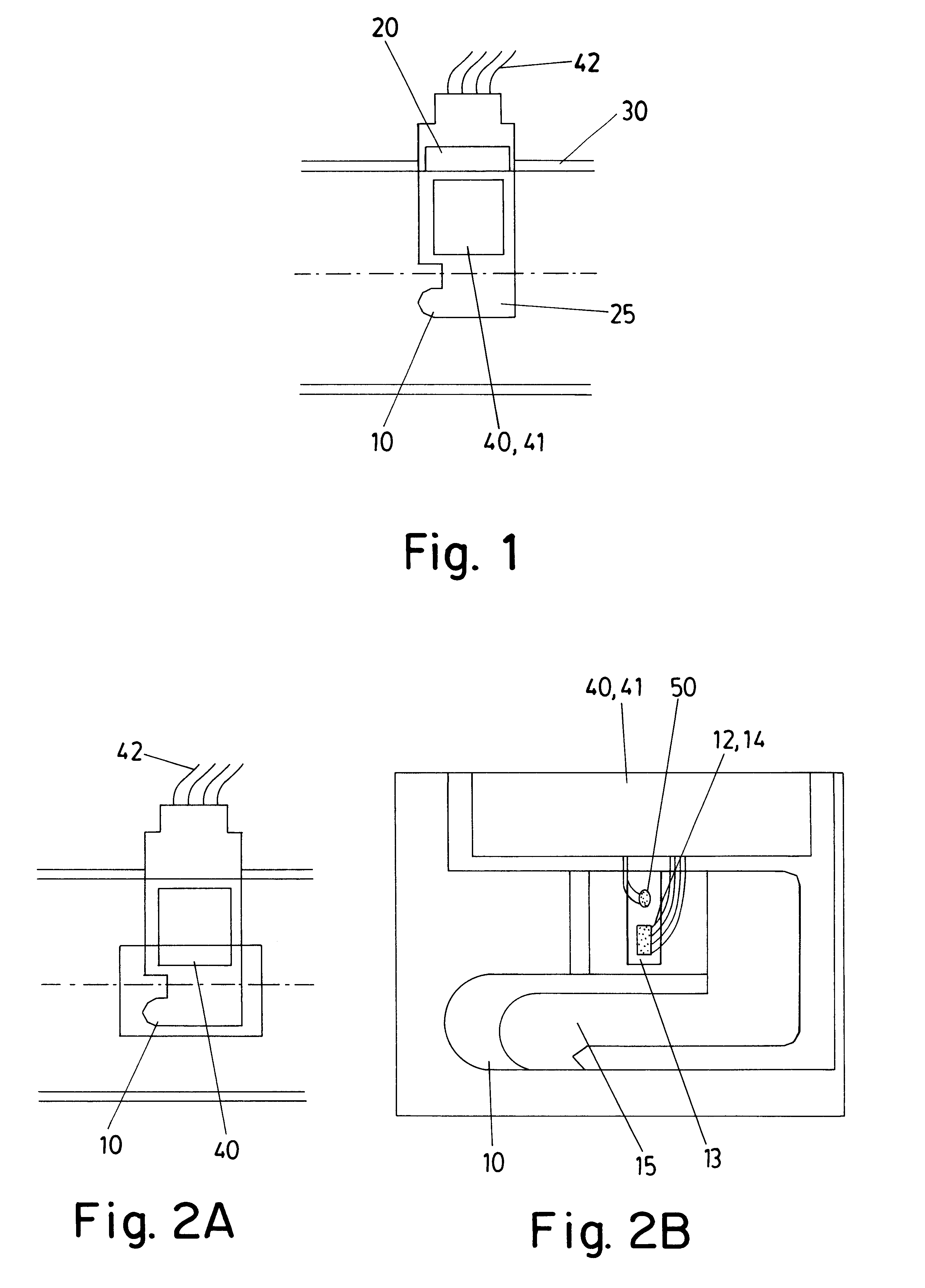
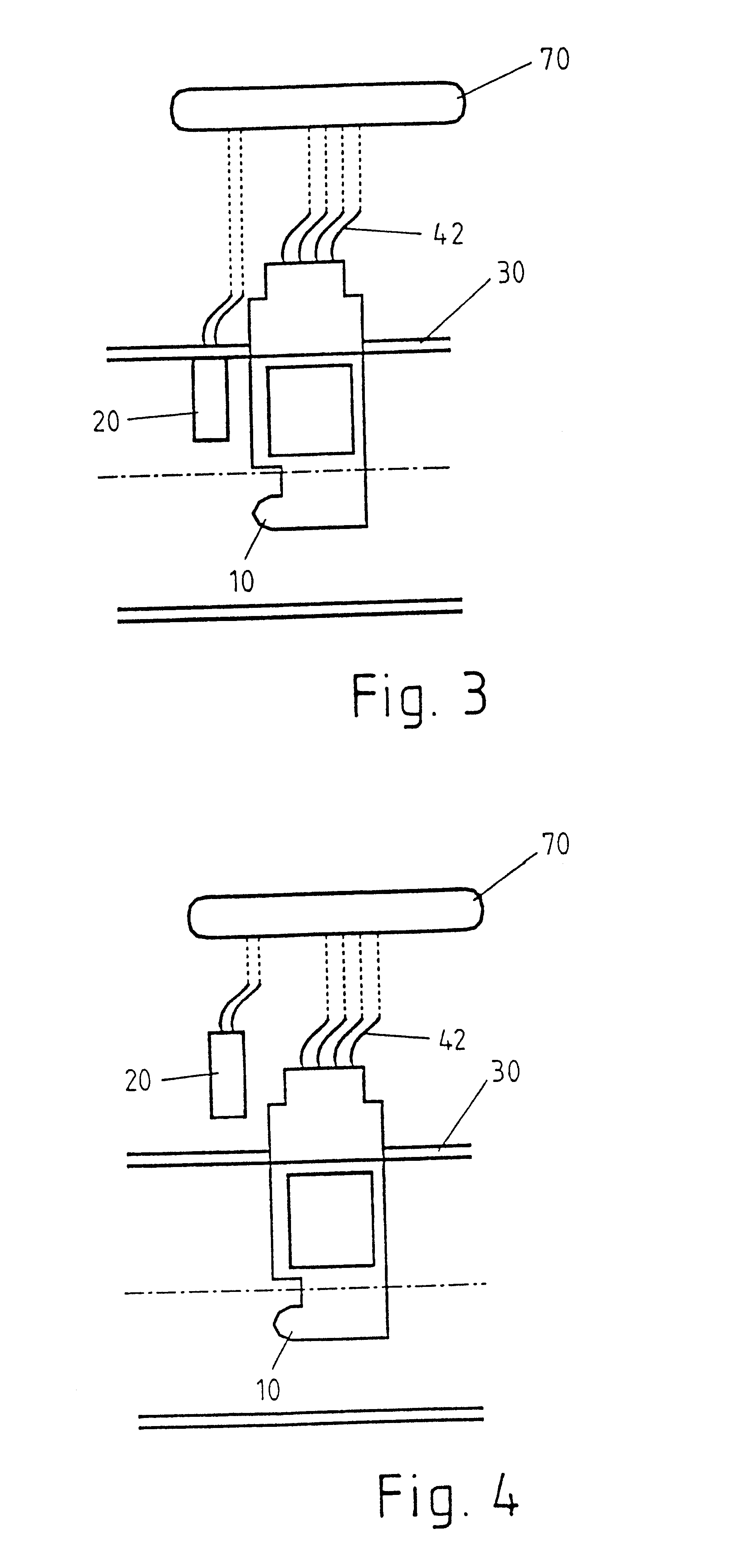
In FIG. 1, a combination of an air flow rate meter 10, known per se, and a humidity sensor 20, known for instance from German Patent Disclosure DE 38 29 517 A1, which are disposed in an intake tube 30 of an internal combustion engine, is shown. In the exemplary embodiment shown in FIG. 1, the air flow rate meter 10 and the humidity sensor 20 are the subject of a single housing (25), in which an electronic evaluation circuit, made by hybrid technology, for instance, is accommodated, which circuit evaluates the data detected by the air flow rate meter 10 and the humidity sensor 20 and outputs it over lines 42, for instance to a control unit (not shown in FIG. 1).

As FIGS. 2A and 2B show in further detail, the air flow rate meter 10 has a temperature-sensitive sensor means 14, which is embodied as a micromechanical component. An air flow rate meter equipped with such a sensor element is known to one skilled in the art from German Patent DE 44 07 209 C2, whose disclosure is hereby expres...


PUM


Abstract

In a method for determining the air aspirated by an internal combustion engine, in which the air flow rate is detected by an air flow rate meter, simultaneously with the detection of the air flow rate, the humidity and / or pressure of the air is detected by a humidity and / or pressure sensor and evaluated in an evaluation circuit.

Description

PRIOR ARTThe invention relates first to a method for determining the air aspirated by an internal combustion engine, in which the air flow rate is detected by an air flow rate meter.It has long been known that the air flow rate aspirated by an internal combustion engine of a motor vehicle can be detected by means of an air flow rate meter. The air flow rate detected is processed in an engine control unit together with other data relevant to the combustion process, such as the temperature of the intake tube pressure, for calculating injection times and the like.One problem in such known methods for determining the air aspirated by an internal combustion engine is that in determining the air flow rate, variables that effect the air flow rate are ignored. One such variable that changes the air flow rate is the humidity, for instance. If the ambient air is very humid, the humidity makes the air flow rate detected by the air flow rate meter wrong, because not only the air that can be com...

Claims


Application Information

Patent Timeline
Patent Type & Authority Patents(United States)
IPC IPC(8): F02D41/18F02D41/00F02D41/24G01F1/684G01F1/68F02D35/00F02D45/00
CPCF02D41/18G01F1/6845F02D41/28F02D2200/0418
Inventor STROHRMANN, MANFREDMUELLER, WOLFGANGKONZELMANN, UWEMUSSERT, PIET-CHRISTIAAN
Owner VOLKSWAGEN AG
Why Eureka
Try Eureka