Zoom lens and optical device using the same

a technology of optical devices and zoom lenses, applied in the field of zoom lenses and optical devices, can solve the problems of increased variations of aberrations upon zooming, difficult to obtain high-quality images, and increased difficulty in obtaining high-quality images

Inactive Publication Date: 2003-07-01
CANON KK
View PDF44 Cites 13 Cited by
  • Summary
  • Abstract
  • Description
  • Claims
  • Application Information

AI Technical Summary

Benefits of technology

Another object of the present invention is to provide a zoom lens in which the size of the overall lens system is reduced in spite of a zoom magnification ratio being as high as on the order of 10. Still another object of the present invention is to provide a zoom lens which has high optical performance and comprises fewer lenses while having a large aperture ratio, with the F-number being about 1.6.

Problems solved by technology

Unless, for example, moving conditions of each lens unit in zooming, a refractive power of each lens unit, a lens arrangement of each zooming lens unit, a selection of one or more lens units for focusing and a lens arrangement of each selected lens unit, an optical action of an aperture stop, etc. are properly set, aberrations that occur upon zooming and focusing increase to such an extent that it is difficult to obtain a high-quality image while realizing a high zoom magnification ratio.
Simply intensifying refractive power of each lens unit, however, raises a problem that variations of aberrations upon zooming are increased and it is difficult to obtain high optical performance over a full zooming range.
However, variations of aberrations upon zooming are increased, which makes it very difficult to obtain high optical performance over the entire range of a distance to an object, ranging from an infinite object to a proximity object, while realizing a size reduction of the overall lens system.

Method used


Image

  • Zoom lens and optical device using the same
  • Zoom lens and optical device using the same
  • Zoom lens and optical device using the same

Examples


second embodiment

the present invention will be described below.

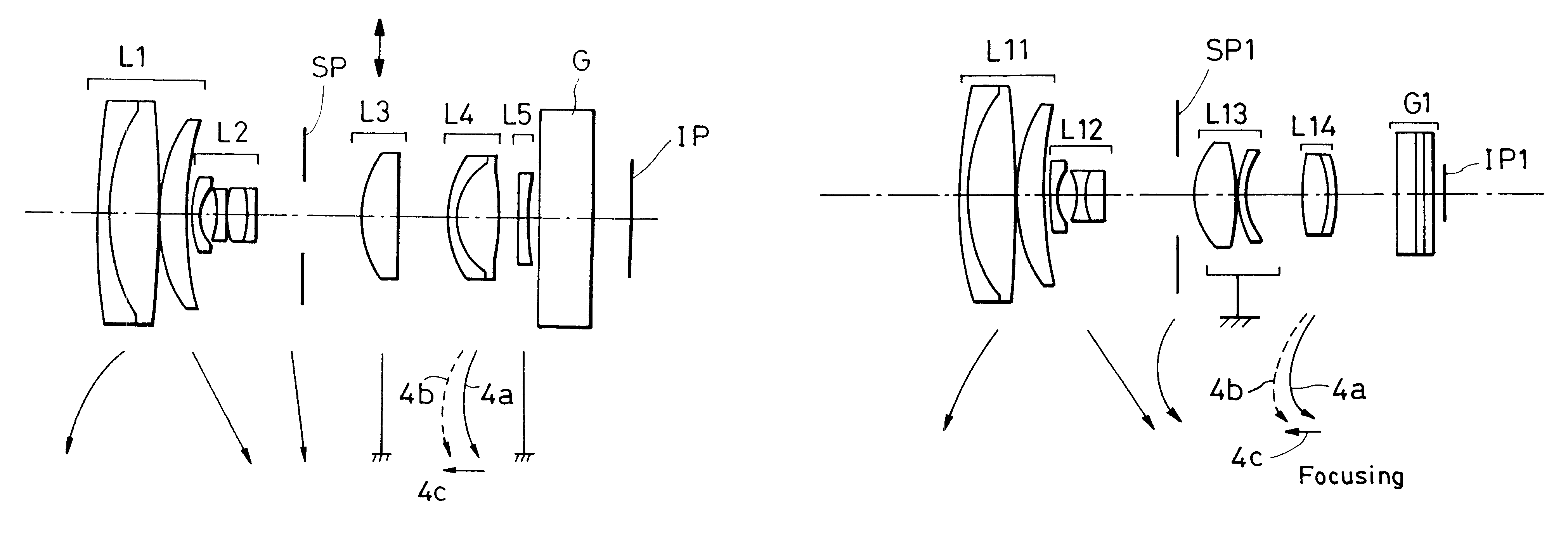
FIGS. 13, 17 and 21 are explanatory views of a zoom lens according to this second embodiment.

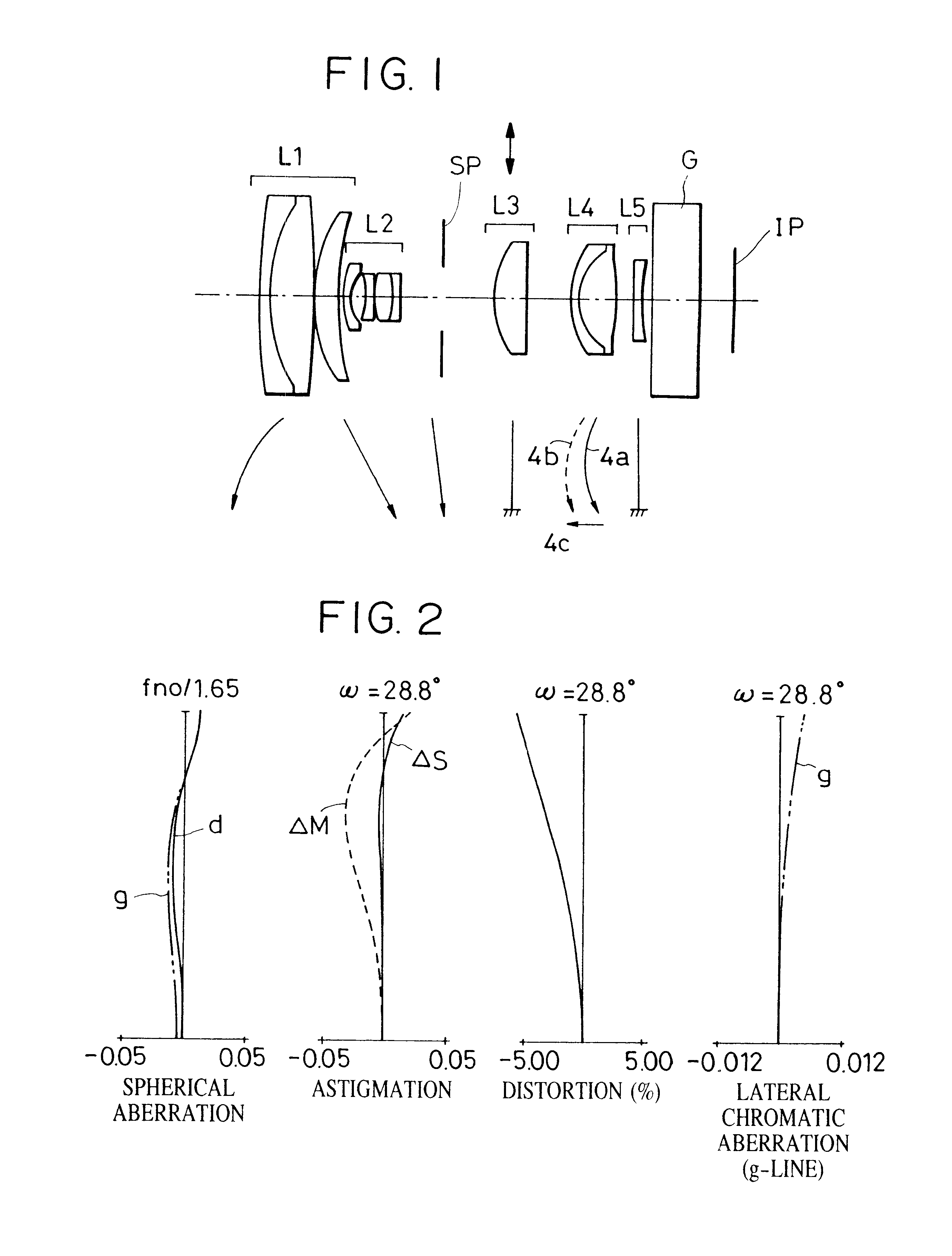
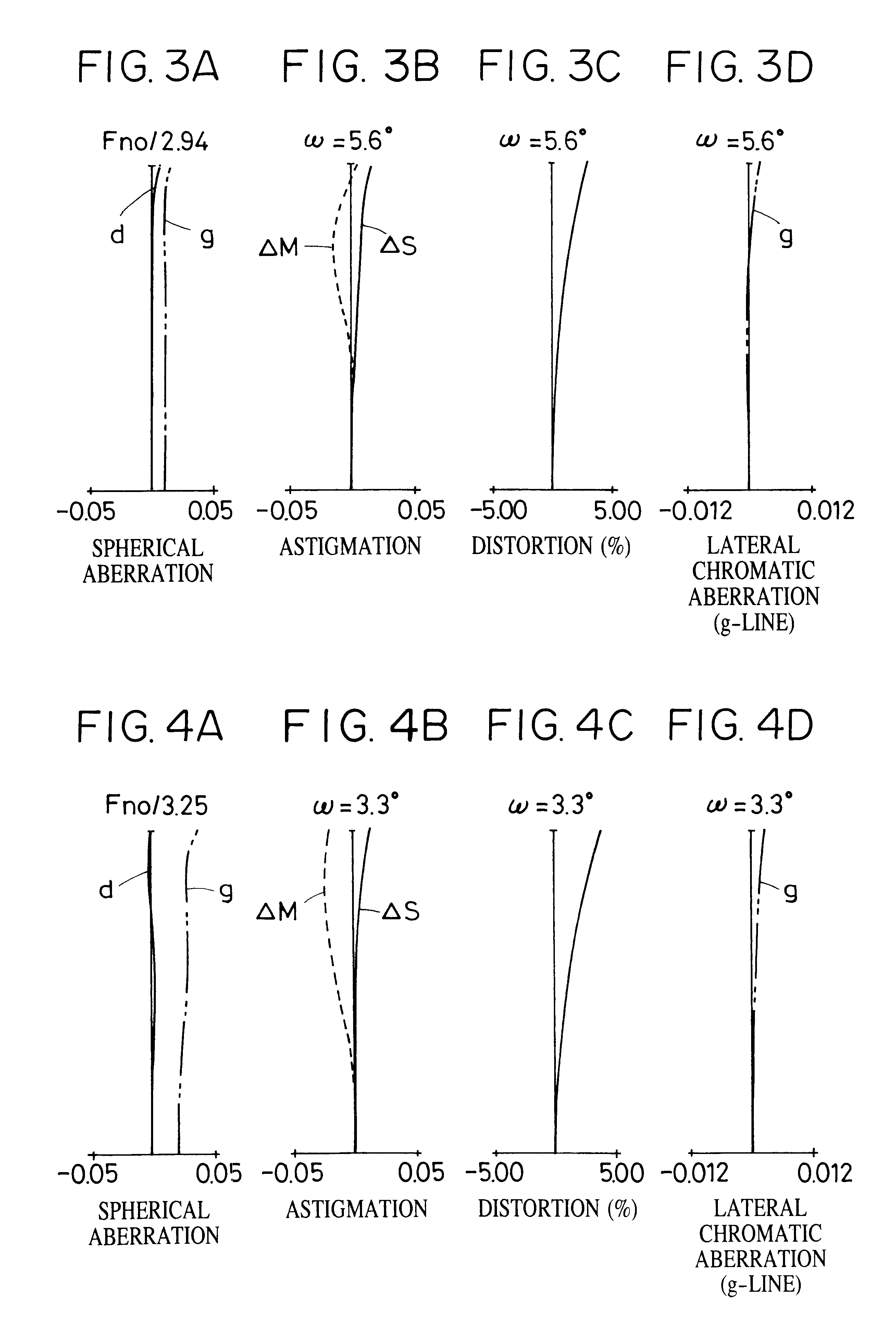
More specifically, FIG. 13 is a sectional view of principal parts of a lens represented by Numerical Value Example 4 of the present invention, and FIGS. 14A to 16D represent aberrations at the wide-angle end, the medium zoom position, and the telephoto end in Numerical Value Example 4, respectively. FIG. 17 is a sectional view of principal parts of a lens represented by Numerical Value Example 5 of the present invention, and FIGS. 18A to 20D represent aberrations at the wide-angle end, the medium zoom position, and the telephoto end in Numerical Value Example 5, respectively. FIG. 21 is a sectional view of principal parts of a lens represented by Numerical Value Example 6 of the present invention, and FIGS. 22A to 24D represent aberrations at the wide-angle end, the medium zoom position, and the telephoto end in Numerical Value Example 6, respect...

example 1

NUMERICAL VALUE EXAMPLE 1

Aspherical Surface Coefficients

example 2

NUMERICAL VALUE EXAMPLE 2

Aspherical Surface Coefficients


PUM


Abstract

A zoom lens comprises a first lens unit having positive refractive power, a second lens unit having negative refractive power, an aperture stop, a third lens unit having positive refractive power and kept fixed during zooming, a fourth lens unit having positive refractive power, and a fifth lens unit having negative refractive power, which are arranged in this order from an object side. In zooming from a wide-angle end to a telephoto end, the second lens unit is moved toward an image plane side such that a spacing between the first lens unit and the second lens unit is increased, and the aperture stop is also moved.

Description

1. Field of the InventionThe present invention relates to a zoom lens and an optical device using the zoom lens, which is particularly suitable for use in optical equipment such as electronic cameras, including a video camera and a digital still camera, and film cameras. Also, the present invention relates to a zoom lens, which has a short overall length and a large aperture ratio with the F-number being about 1.6 at the wide-angle end while it has a zoom magnification ratio as high as on the order of 10, and an optical device using the zoom lens.2. Description of the Related ArtHitherto, a zoom lens having a relatively small overall lens system and a relatively high zoom magnification ratio has been proposed in, e.g., Japanese Patent Laid-Open Nos. 56-114920 and 58-160913 (U.S. Pat. No. 4,720,180). This zoom lens comprises four lens units, i.e., a first lens unit having positive refractive power, a second lens unit having negative refractive power, a third lens unit having positive...

Claims


Application Information

Patent Timeline
Patent Type & Authority Patents(United States)
IPC IPC(8): G02B15/163G02B15/173
CPCG02B15/173G02B15/145113
Inventor HORIUCHI, AKIHISA
Owner CANON KK
Why Eureka
Try Eureka