Curved line fill stitching in embroidery designs

a technology of curved lines and embroidery designs, applied in embroidering machines, automatic machines, embroidering machines, etc., can solve the problems of complex shape 10, embroidery designers can't use curved lines to fill areas very much, and cannot do a good job of automatically filling areas with a series of automatically calculated curved lines

Inactive Publication Date: 2003-07-01
WILCOM
View PDF5 Cites 24 Cited by
  • Summary
  • Abstract
  • Description
  • Claims
  • Application Information

AI Technical Summary

Problems solved by technology

The shape 10 is complex because it is not possible to fill it with an uninterrudted series of straight lines of stitching.
However, while existing embroidery design systems can calculate stitching along individual curved lines, that is outlines, quite well, they cannot do a good job in automatically filling areas with a series of automatically calculated curved lines.
As a result embroidery designers can't use curved lines to fill in areas very much.
But this technique has several very serious limitations, which restricts its use to a small number of special cases.
There are many limitations to this type of stitching: The stitch density between adjacent lines of stitching varies greatly across the shape because the same number of stitch lines are used in wide areas and narrow areas.
The narrow parts have too many stitches, see the narrow end 7, which cause thread breaks and production problems, it takes much longer to stitch because of the additional stitches and the look of the finished embroidery is uneven.
The visual pattern of intermediate stitch points often has noticeable discontinuities 8 in it resulting in an uneven visual effect, and is seen as undesirable, poor quality embroider.
Using contour stitching, it is not possible to use stitch techniques such as "program split" or "motif fill" inside the shape, and it is not possible to have holes without stitching inside the filled shape.
Embroidery design systems have had the capability to perform automatic "complex fill" with straight line stitching techniques as early as 1989. and have been able to perform "contour type" curved stitching for about as long, but it has not heretofore been possible to have curved line stitching which satisfies the conflicting requirements of consistent density, consistent visual effect of intermediate stitch points, and curved stitching lines independent of the shape to be filled.

Method used


Image

  • Curved line fill stitching in embroidery designs
  • Curved line fill stitching in embroidery designs
  • Curved line fill stitching in embroidery designs

Examples


example 2

A Single Curve is Entered

This variation of the invention uses almost the same steps as above, with a few exceptions. First, only one curve 180 is specified, as can be seen in FIG. 18. However, two stitch definition curves are still used in the calculations, but they are calculated based on the single stitch definition curve specified, in a manner described below. The curves are calculated such that a uniform stitch density is provided across the shape being filled.

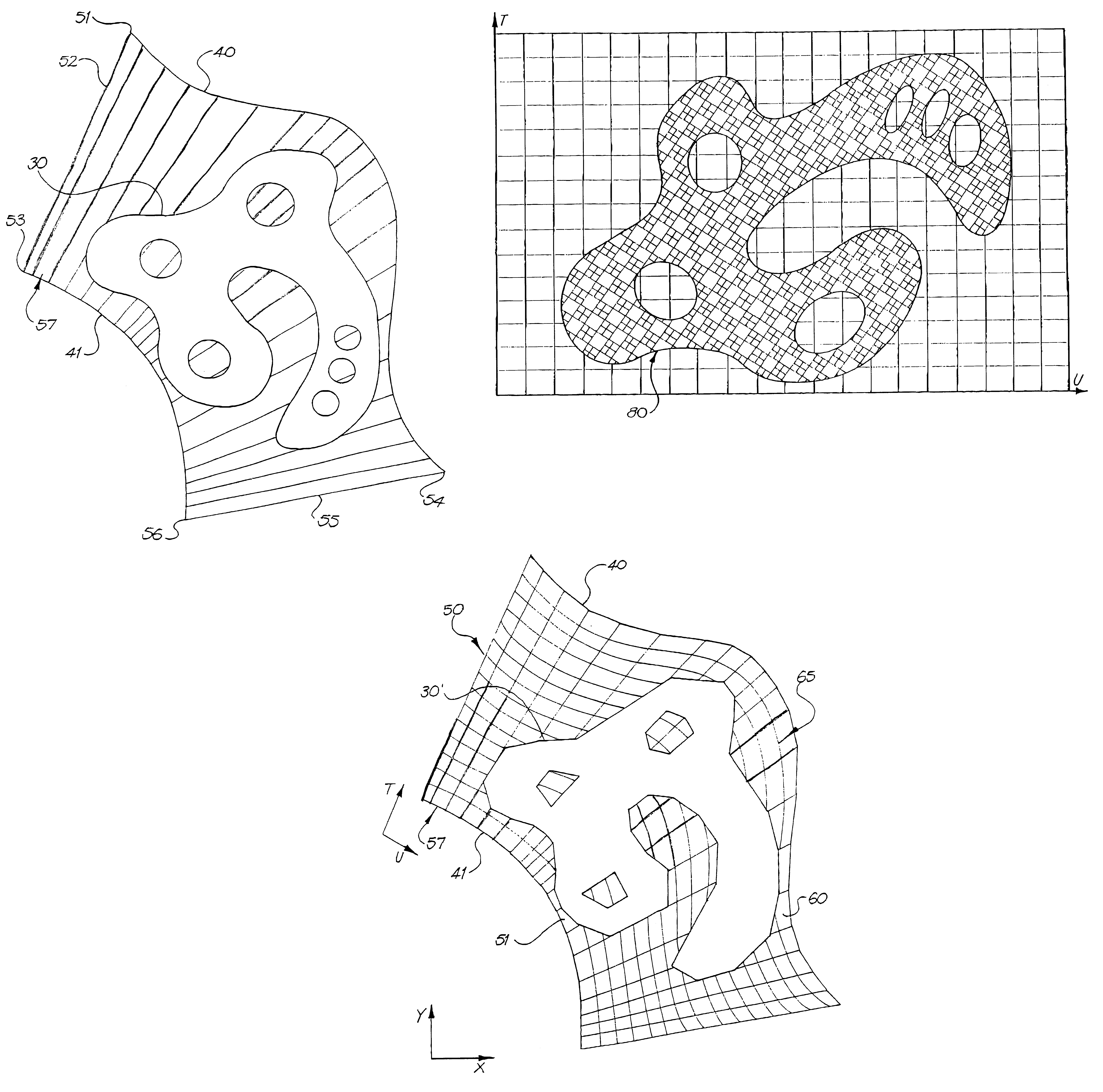
Now we discuss the problem of generating curved stitching on a complex-fill shape from a single stitch definition curve. The technique is to derive from this single curve 180 two new stitch definition curves which bound the complex fill region; the stitching is then generated using the two-curve form of the invention, i.e. following u-co-ordinate lines between the two new curves.

The two new curves meet two key requirements; they are chosen in such a way as to minimise the variation in the distance between the U-co-ordinate...


PUM


Abstract

This invention concerns automatically generating embroidery stitch patterns in a computer aided design system where areas defined by vector outline shapes are filled with stitches which follow curved lines rather than straight lines. This is done in a way to maintain consistent densities and consistent needle penetration patterns inside the areas. The shapes of the areas may be simple polygons which can be filled in one contiguous segment of curved stitching, or they may be complex or multi-boundary shapes which must be stitched in more than one distinct segments of curved line stitching. The areas are transformed into another coordinate space where known calculation methods for straight line stitching are used to calculate straight line fills of the transformed area. The resulting area and stitches are then transformed back to the original coordinates, resulting in even stitching along smooth curves which fills the original area such that the intermediate stitch penetration points along the curves form a smooth continuous visual pattern throughout the area.

Description

The present invention relates generally to the generation of an embroidery design in a computer aided design system. Such designs involve stitching instructions that are used by automatic embroidery machines to embroider designs. In particular the invention concerns a method for generating an embroidery designs. In a second aspect the invention is a system for generating an embroidery design. In a third aspect the invention is a series of stitch commands for controlling an automatic embroidery machine so that it is able to perform the method.DESCRIPTION OF PRIOR ARTAutomatic embroidery machines are very well known in the embroidery industry. The primary characteristics of automatic embroidery machines, and the basic manner in which embroidery designs are defined for these prior art machines is described in the book. "Embroidery: Schiffli & Multihead", by Coleman Schneider, 1978. International Standard Book Number 0-9601662-1-1.An automatic embroidery machine typically operates by mo...

Claims


Application Information

Patent Timeline
Patent Type & Authority Patents(United States)
IPC IPC(8): D05B19/08D05B19/00G06F17/50
CPCD05B19/08
Inventor POLDEN, ALEXANDERWILSON, WILLIAM BRIAN
Owner WILCOM
Why Eureka
Try Eureka