
Hanging device

Inactive Publication Date: 2003-07-08
CHEN CHIA TEH
View PDF4 Cites 10 Cited by
  • Summary
  • Abstract
  • Description
  • Claims
  • Application Information

AI Technical Summary

Benefits of technology

to provide a hanging device with internal lighting that is firmly mounted in the closet with a reduced occupation space. The hanging device of the invention is compact and has a reinforced structure, thereby taking into account both esthetic and practical aspects. Additionally, the hanging device also provides good illumination.
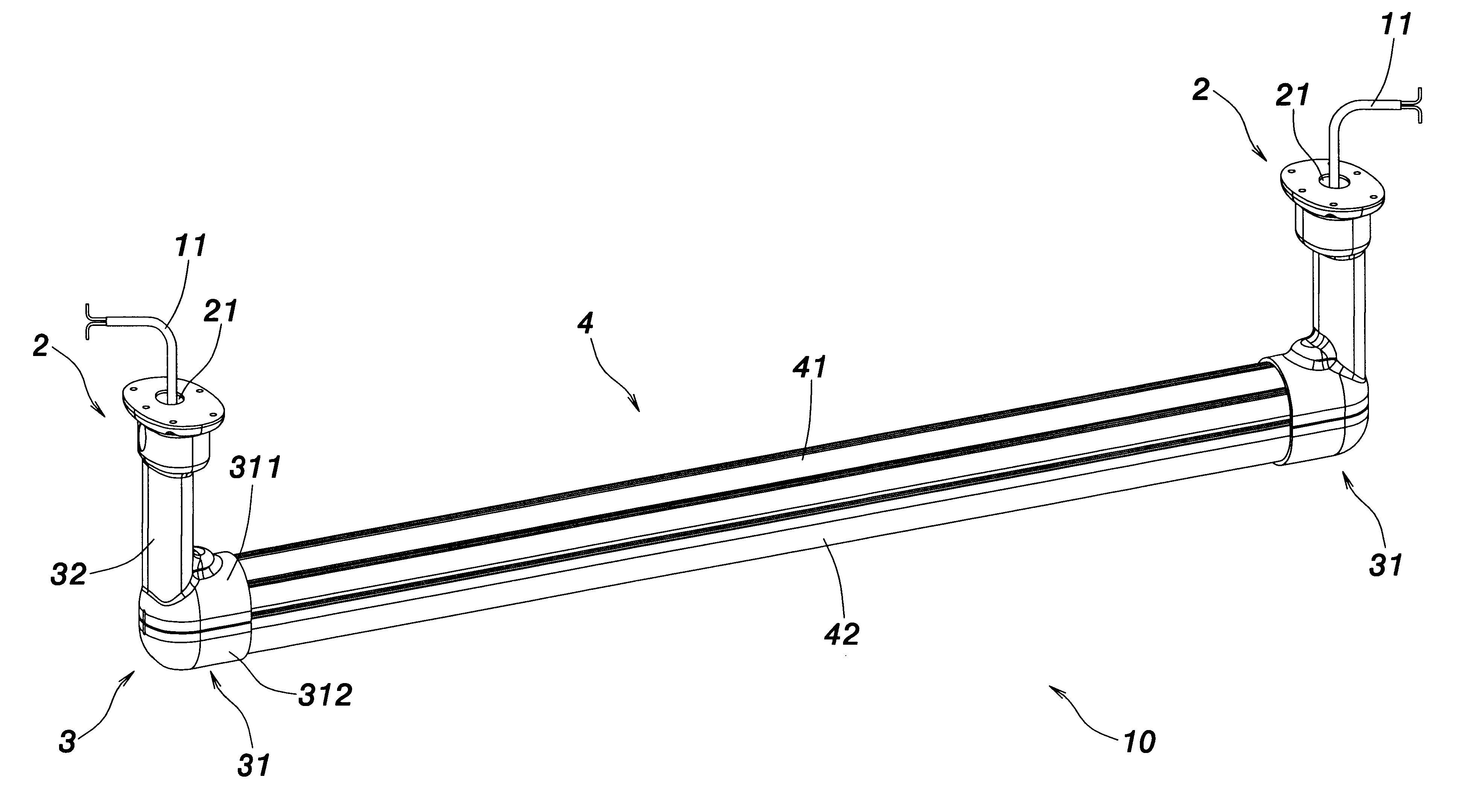
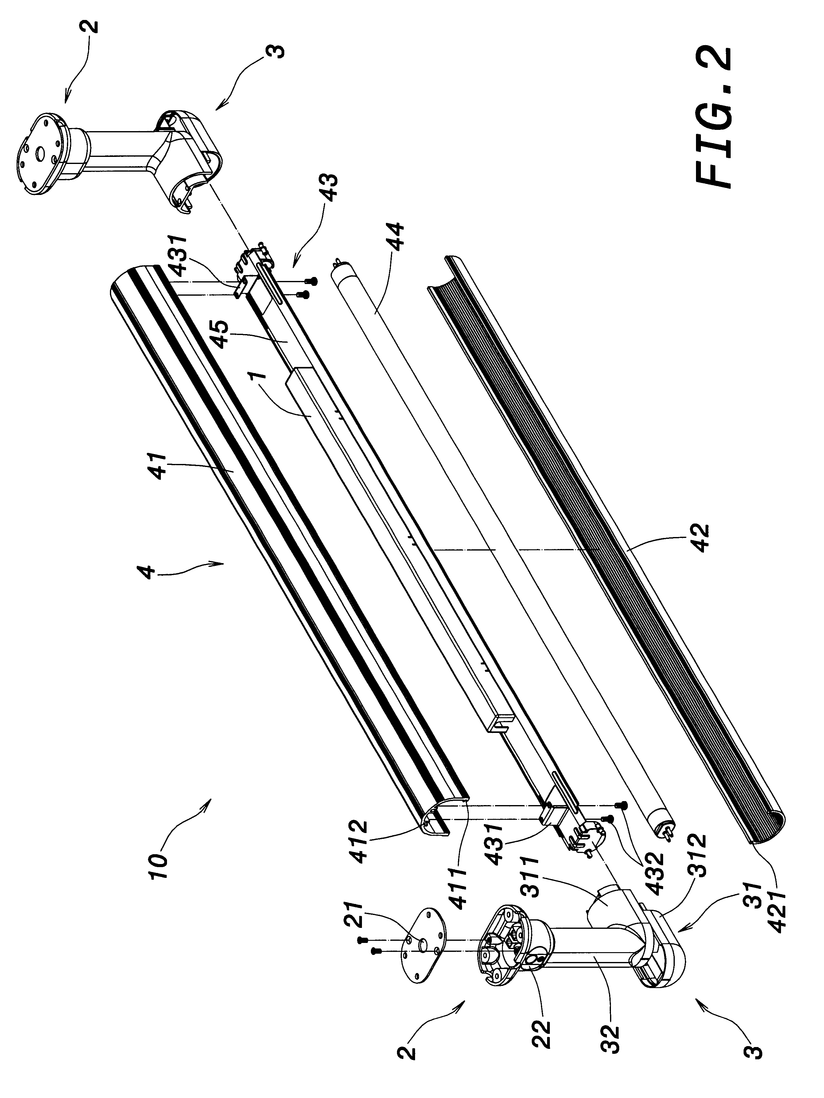
According to one aspect of the invention, the hanging device comprises a support member, two fixtures, two adjustment units and a hanging rod. The hanging rod includes a cover and a lampshade. A support base, which has a fluorescent tube mounted at a bottom thereof and the support member mounted at a top thereof, is located between the cover and the lampshade. Therefore, the support member does not occupy any external space out of the hanging rod, resulting in an esthetic and compact structure.
Each of the adjustment units includes a connection body and a vertical connector that is vertically connected to one end of the connection body. One connection body comprises a stationary lid and a slidable lid. Each end of the cover of the hanging rod 4 engages one stationary lid. The slidable lids of each connection body are detachably connected to each end of the lampshade. When the fluorescent tube is to be replaced, only the slidable lids are needed to outwardly slide for separating from the lampshade. Thereafter, the lampshade is pressed inward to detach the engagement slots of the lampshade from the engagement slots of the cover, so that the lampshade is easily separated from the hanging rod for replacing the fluorescent tube.

Problems solved by technology

The light from the lighting of the ceiling in the closet is easily barred, resulting in insufficient illumination for a good visibility.
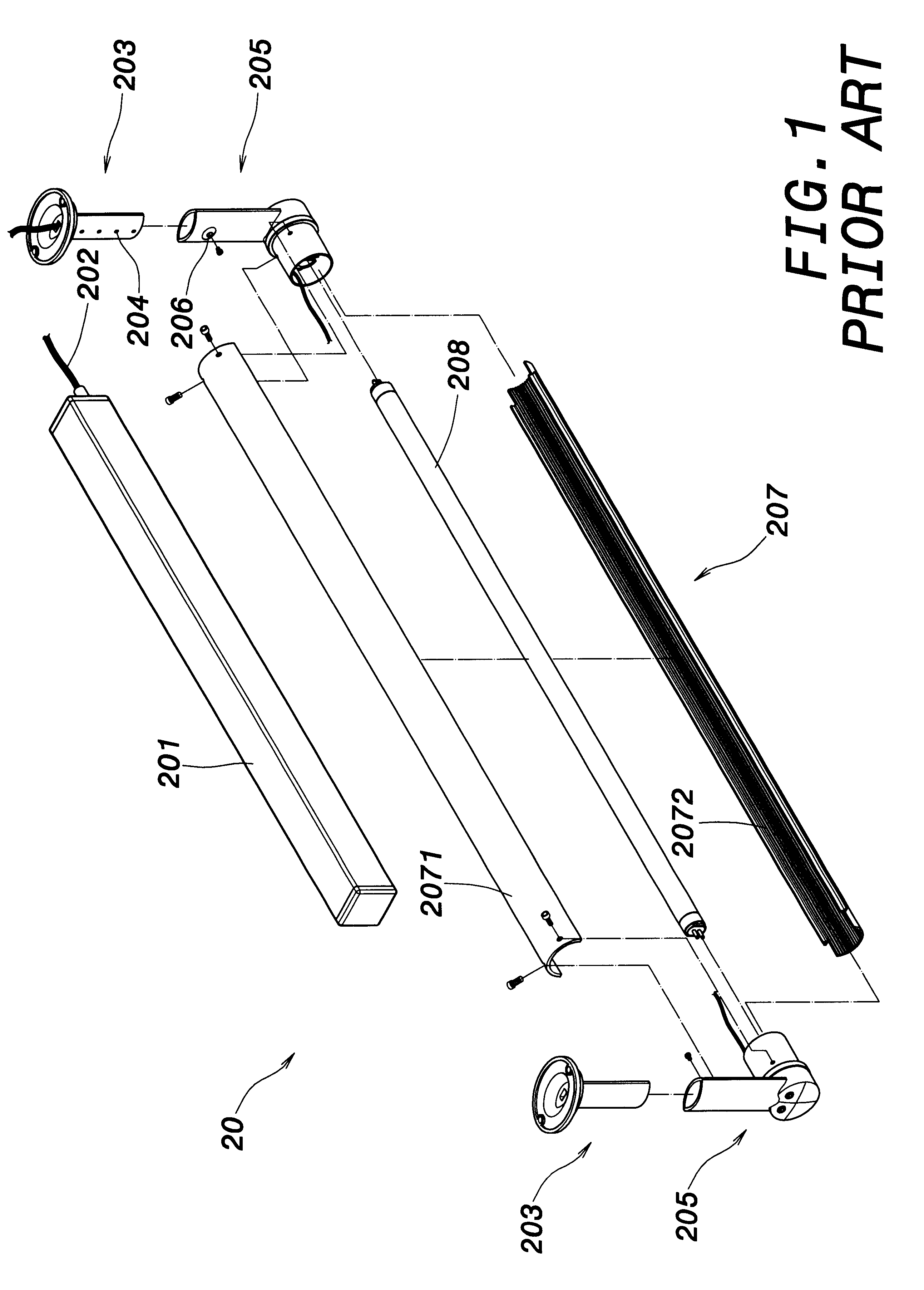
This may be dangerous because the fluorescent tube 208 may also break.
Furthermore, the hanging device cannot provide further support for receiving additional elements such as hanging rods and internal power supplies.

Method used


Image

  • Hanging device
  • Hanging device
  • Hanging device

Examples


first embodiment

FIG. 5 is a schematic view of a hanging device in use according to the invention. In use configuration, the fixture 2 is fixed to the shelf, as shown in FIG. 5. Clothing is hung on the hanging rod 4 provided with the support member 1 therein. The hanging rod 4 is reinforced by means of the rib 412 as well as the engagement slots 411, 421 that also serve as reinforcement elements. Additionally, the fluorescent tube 44 inside the hanging rod 4 provides good illumination.

FIG. 6 is a view showing a replacement of a fluorescent tube according to the first embodiment of the invention. When the fluorescent tube 44 is to be replaced, only the slidable lid 312 is needed to slide outward to separate from the lampshade 44. Thereafter, the lampshade 44 is pressed inward to detach the engagement slots 421 of the lampshade 42 from the engagement slots 411 of the cover 41, the lampshade 42 is thereby easily separated from the hanging rod 4 for replacing the fluorescent tube 44.

second embodiment

FIG. 7 is a schematic view of a hanging device according to the invention. In FIG. 7, two hanging devices 10, 10' similar to those shown in FIG. 2 through FIG. 4 are electrically connected in series. A socket 22 as shown in FIG. 2 is provided at a right end of each of the hanging devices 10, 10', and an electric plug as shown in FIG. 2 is provided at a left end of each of the hanging devices 10, 10'. The electrical plug 23 of the hanging device 10' is inserted into the socket 22 of the hanging device 10 without the power wire 11. More than two hanging devices can be connected in the manner described above, avoiding the exposure of any power wire.

third embodiment

FIG. 8 is schematic view of a hanging device according to the invention. An automatic sensor 5 connected to the hanging device 10 can be further provided in the closet. In FIG. 8, the automatic sensor 5 is located on the power wire 11 extended from the fixtures 2. The sensor 5 detects whether the closet is opened, and consequently turns on the fluorescent tube of the hanging device 10 if the closet is opened.


PUM


Abstract

A hanging device comprises a support member, two fixtures, two adjustment units and a hanging rod. The hanging rod includes a cover and a lampshade that enclose a fluorescent tube and the support member. The adjustment units are detachably engaged with the lampshade for easily replacing the fluorescent tube. More than one of the hanging devices can be electrically connected in series by providing each hanging device with a socket and an electrical plug on ends thereof.

Description

1. Field of the InventionThe invention relates to a hanging device. More particularly, the invention relates to a hanging device that has improved hanging and illumination functions.2. Description of the Related ArtA conventional closet is usually provided with lighting and hanging devices. In most of the cases, the lighting is mounted on a ceiling of the closet. The hanging device is usually located between two sidewalls of the closet for hanging clothing or the like. A plurality of drawers may be further provided inside the closet. The light from the lighting of the ceiling in the closet is easily barred, resulting in insufficient illumination for a good visibility.Taiwan Patent Application No. 90213540 is filed by the same applicant of the present application, and the disclosure thereof is incorporated herein by reference. The above-cited Taiwan Patent Application discloses a hanging device provided with a lighting thereon. FIG. 1 is an exploded view of a hanging device of the pr...

Claims


Application Information

Patent Timeline
IPC IPC(8): F21V33/00F21S2/00
CPCA47B61/003F21V33/0012F21S2/00F21Y2103/00
Inventor CHEN, CHIA-TEH
Owner CHEN CHIA TEH
Learn More