
Transmission equipped with planetary gear mechanism and planetary gear mechanism

a technology of planetary gear mechanism and planetary gear mechanism, which is applied in the directions of gearing details, transportation and packaging, gearing, etc., can solve the problems of axial deviation of the sun gear and the carrier to be fixed to these power transmission members, the axial position of the sun gear and the carrier to be fixed to the power transmission member also deviating

Inactive Publication Date: 2003-07-15
HONDA MOTOR CO LTD
View PDF8 Cites 12 Cited by
  • Summary
  • Abstract
  • Description
  • Claims
  • Application Information

AI Technical Summary

Benefits of technology

In view of the above points, the present invention has another object of providing a planetary gear mechanism which has a smaller space in the axial direction and which has an improved workability in assembling.
When the first and second engaging portions are engaged together, the power transmission member is prevented by the pinion shaft from rotating relative to the carrier. In addition, the pinion shaft is prevented by the power transmission member from rotating relative to the carrier in a predetermined phase. In this manner, simply by preventing, with a suitable means, the power transmission member and the pinion shaft from being axially pulled out of position relative to the carrier, the power transmission member and the pinion shaft can be fixed by preventing them from rotating relative to the carrier. Therefore, a troublesome work of fixing the power transmission member and the pinion shaft to the carrier such as welding or riveting is no longer required, with the result that the assembly work of the carrier becomes easy. In particular, if a first snap ring is mounted on the supporting portion so as to prevent the power transmission member from being pulled out of position relative to the supporting portion, and if a second snap ring is mounted on the pinion shaft so as to prevent the pinion shaft from being axially pulled out of position to thereby prevent the power transmission member and the pinion shaft from being axially pulled out of position, the assembly work of the carrier is further improved.

Problems solved by technology

However, in the above-described conventional transmission in which that element of the planetary gear mechanism which is to be fixed is fixedly engaged by a snap ring in a manner not to be movable in the axial direction, there is the following disadvantage.
Namely, if another transmission constituting element is present on this side of the planetary gear as seen from an open end of the transmission casing, this transmission constituting element in question will be an obstacle to the mounting of the snap ring.
As a consequence, the assembly work of the transmission constituting elements into the transmission casing must be made from the innermost element in sequence toward the outermost element, resulting in a troublesome assembly work of the transmission.
However, in the above-described conventional art, if the power transmission member on one axial side and the power transmission member on the axially opposite side deviate in the axial position, the axial position of the sun gear and the carrier to be fixed to these power transmission members also axially deviate.
As a result, there is a disadvantage in that the planetary gear mechanism occupies a larger axial space.
Therefore, it takes time to assemble the carrier.
If the sun gear and the carrier are assembled in the steps of assembling the transmission as in the conventional way, the assembling work of the transmission becomes troublesome.
As a result, it takes much time in assembling the carrier, resulting in a high cost.
Further, if that element of the planetary gear mechanism which is to be fixed is directly fixed to the transmission casing, noises are likely to occur due to the conveyance of the vibrations from this element to the transmission casing.
Therefore, a troublesome work of fixing the power transmission member and the pinion shaft to the carrier such as welding or riveting is no longer required, with the result that the assembly work of the carrier becomes easy.

Method used


Image

  • Transmission equipped with planetary gear mechanism and planetary gear mechanism
  • Transmission equipped with planetary gear mechanism and planetary gear mechanism
  • Transmission equipped with planetary gear mechanism and planetary gear mechanism

Examples


Embodiment Construction

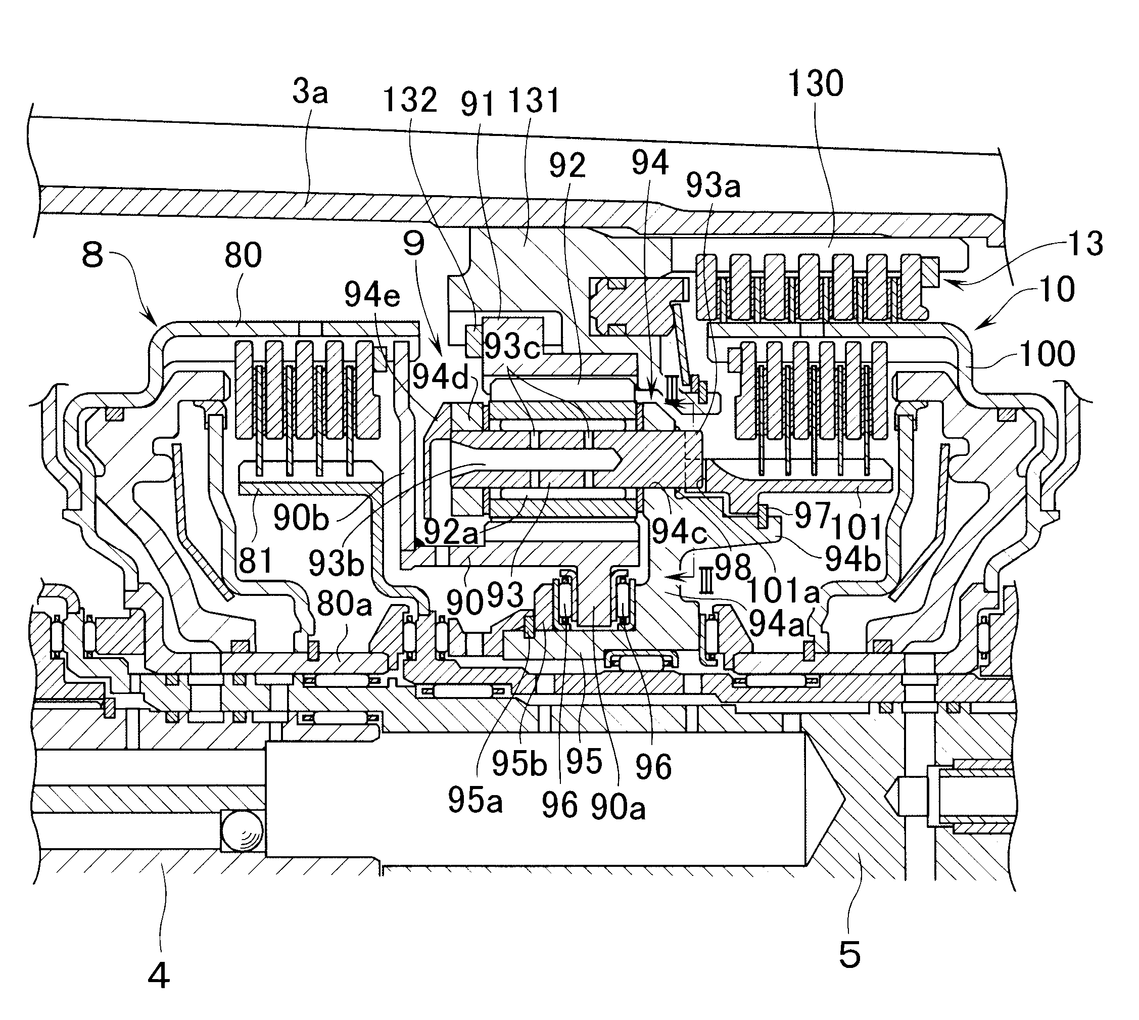
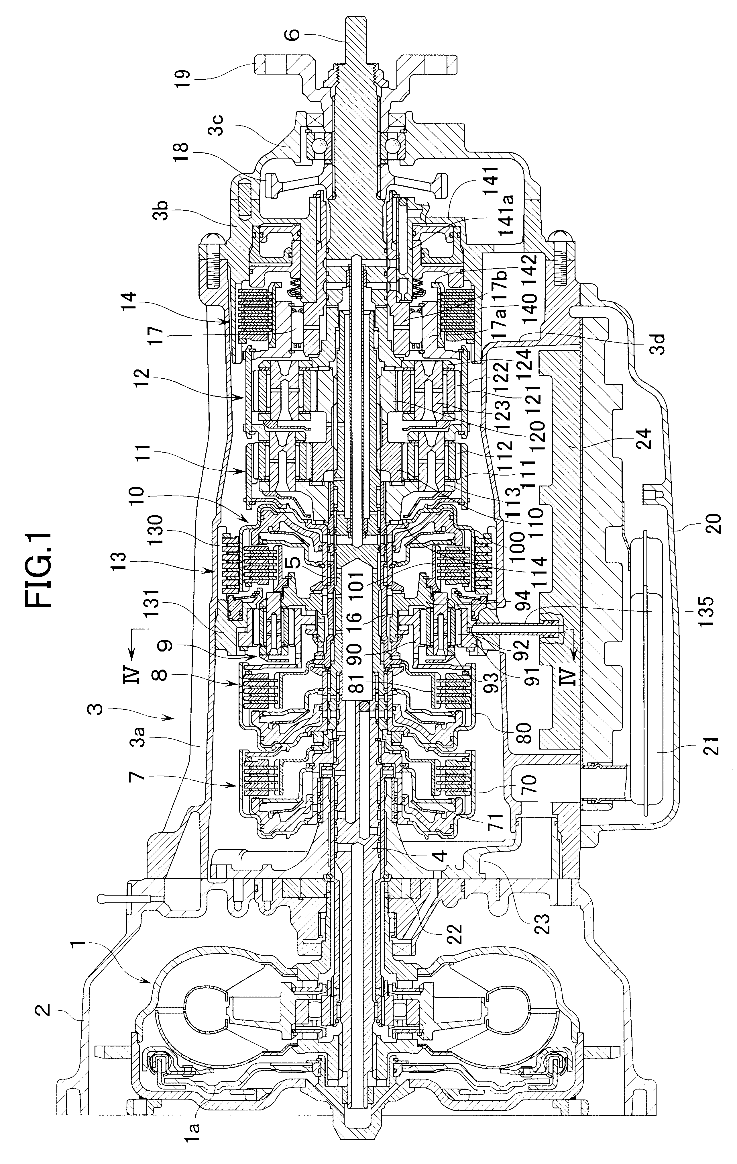
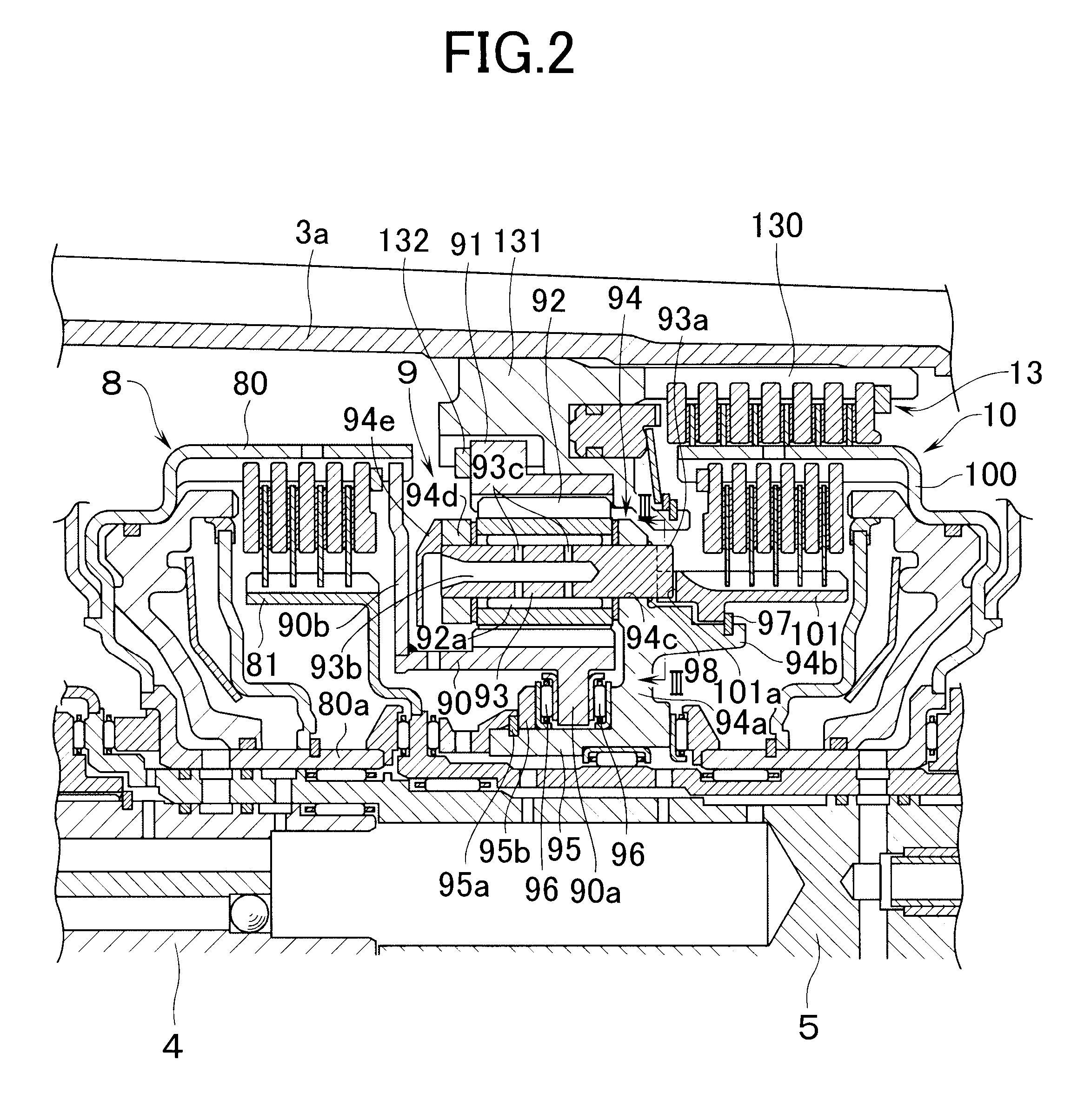
FIG. 1 shows an automatic transmission for a motor vehicle. This transmission is provided with a transmission casing 3 which is coupled to a torque converter casing 2 containing therein a fluid torque converter 1 equipped with a lock-up clutch la. Inside this transmission casing 3, there are rotatably supported on the same axial line an input shaft 4 which is coupled to the fluid torque converter 1, an intermediate shaft 5 and an output shaft 6. Around these shafts 4, 5, 6 there are disposed in the order mentioned, as seen from the side of the torque converter casing 2, a first hydraulic clutch 7, a second hydraulic clutch 8, a first planetary gear mechanism 9, a third hydraulic clutch 10, a second planetary gear mechanism 11 and a third planetary gear mechanism 12. Further, there is disposed a first hydraulic brake 13 around the third hydraulic clutch 10, and a second hydraulic brake 14 is disposed at an axial front of the third planetary gear mechanism 12.

Each of the planetary gea...


PUM


Abstract

In a transmission with a built-in planetary gear mechanism which has an element to be fixed to a casing of the transmission, inner elements are sub-assembled by mounting a plurality of transmission constituting members inclusive of the planetary gear mechanism. After containing the inner elements inside the casing, the element to be fixed is arranged to be fixable to the casing from a peripheral wall portion of the casing. The element to be fixed is fixed to the cylinder portion of a hydraulic brake to be built in the transmission. The cylinder portion is fixed to the casing by means of fixing members which are inserted into the casing from an outside of the peripheral wall portion of the transmission casing.

Description

1. Field of the InventionThe present invention relates to a transmission equipped with a planetary gear mechanism which has an element to be fixed to a transmission casing, and also relates to a planetary gear mechanism.2. Description of Related ArtIn case an element such as a ring gear, a carrier, or the like of a planetary gear mechanism is fixed to a transmission casing in the above-described kind of conventional transmission, the above-described element is engaged with the transmission casing by means of a spline so as not to be rotatable relative to the transmission casing, and is fixedly engaged by a snap ring so as to be relatively immovable in an axial direction (see Japanese Published Unexamined Patent Application No. 203740 / 1989). In order to facilitate the assembling work of the transmission, it is desirable to take the following steps. Namely, in an open space outside the transmission casing, transmission constituting elements including a planetary gear mechanism assembl...

Claims


Application Information

Patent Timeline
Patent Type & Authority Patents(United States)
IPC IPC(8): F16H57/10F16H57/02F16H57/00F16H3/66F16H57/023F16H57/028
CPCF16H57/028F16H57/10F16H3/66F16H57/082F16H2057/02043F16H2057/02047F16H2200/0052F16H2200/201F16H2057/005F16H2057/0235
Inventor TAJIMA, SHIGERUIMAMURA, MASAHIROMORIMOTO, YASUHIRO
Owner HONDA MOTOR CO LTD
Learn More