Method of routing ATM cell in ATM network

a technology of atm network and atm cell, which is applied in data switching networks, time-division multiplexing selection, digital transmission, etc., can solve the problem that the hardware construction of atm network elements becomes very complicated

Inactive Publication Date: 2003-07-15
LG ERICSSON
View PDF0 Cites 10 Cited by
  • Summary
  • Abstract
  • Description
  • Claims
  • Application Information

AI Technical Summary

Problems solved by technology

The ATM adaptation layers over two kinds may be, of course, determined in one ATM network element, but in this case, the construction of the ATM network element becomes very complicated in hardware, so such an actual construction is not executed.

Method used


Image

  • Method of routing ATM cell in ATM network
  • Method of routing ATM cell in ATM network
  • Method of routing ATM cell in ATM network

Examples


Embodiment Construction

Reference will now be made in detail to the preferred embodiments of the present invention, examples of which are illustrated in the accompanying drawings.

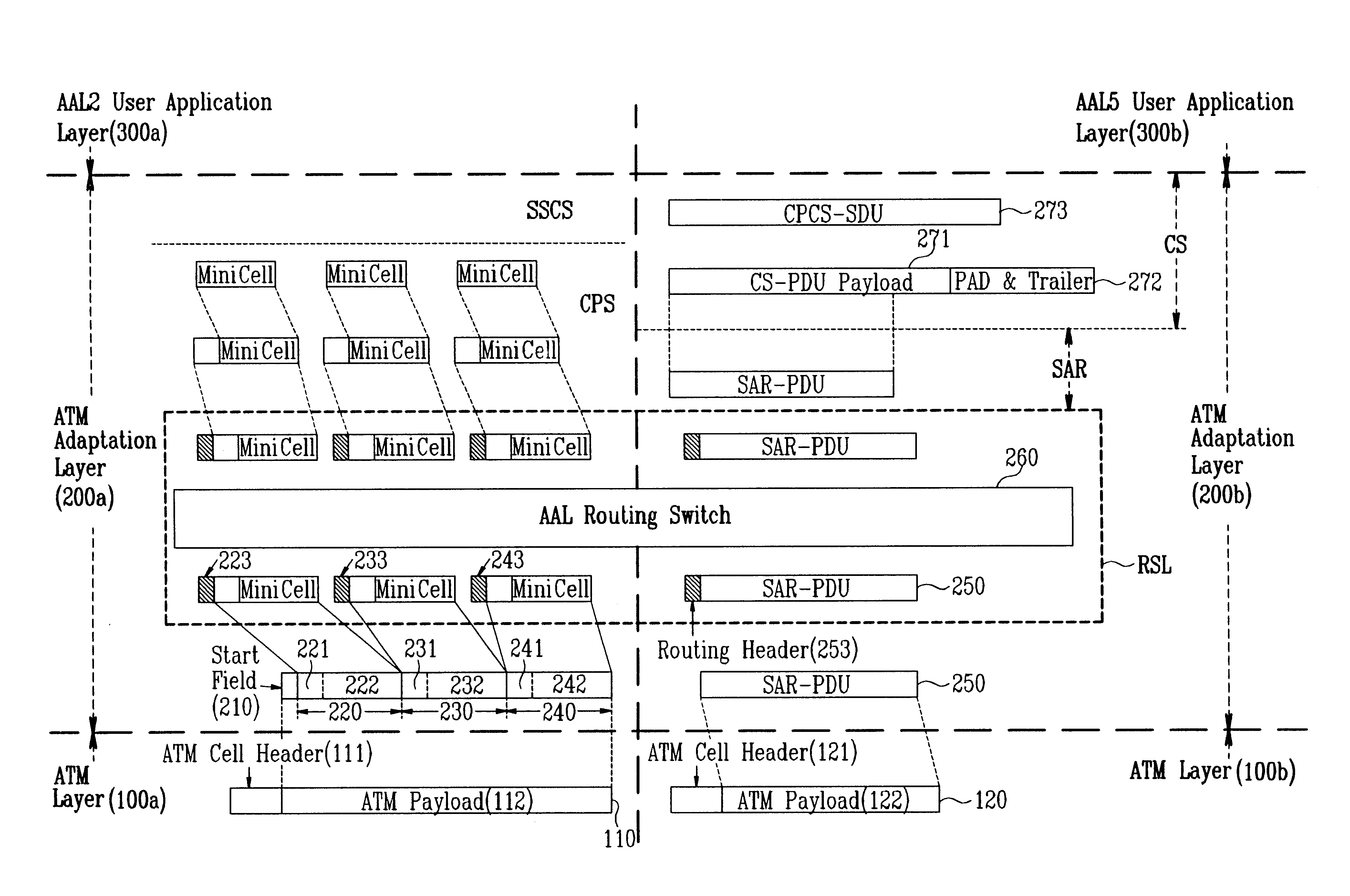
FIG. 3 sets forth a protocol stack for an ATM adaptation layer in accordance with the present invention. Referring to FIG. 3, the protocol stack of the inventive ATM adaptation layer is subdivided into an AAL-Type2 sublayer and an AAL-Type5 sublayer. The AAL-Type2 sublayer and the AAL-Type5 sublayer add each of AAL routing headers 223,233,243,253 up before each of headers 221,231,241 of mini cells 220,230,240 and before an SAR-PDU (250) according to a destination of the ATM adaptation layer in numerous mini cells 220-240 included into one ATM cell 110 transferred from ATM layers 100a, 100b or in one SAR-PDU (Protocol Data Unit) 250. Also, the AAL-Type2 sublayer and the AAL-Type5 sublayer commonly possess an AAL routing switch controlling layer (RSL) for performing a switching to a destination of the ATM adaptation layer according ...


PUM


Abstract

A method of routing an ATM cell in an ATM network and routing an ATM cell and a structure of an ATM adaptation layer in an ATM network. Data based on an ALL-Type2 (ATM Adaptation Layer Type2) and an AAL-Type5 (ATM Adaptation Layer Type5) is transferred to the same destination. This enables data based on ATM adaptation layers of different types to be transferred to the same destination at the same time.

Description

1. Field of the InventionThe present invention relates to a method of routing an ATM cell in an ATM network, and more particularly, to a method of routing an ATM cell and a structure of an ATM adaptation layer in an ATM network in which data based on an AAL-Type2 (ATM Adaptation Layer Type2) and an AAL-Type5 (ATM Adaptation Layer Type5) is transferred to the same destination.2. Discussion of Related ArtIn general, the most basic function in a communication network is to select a desired party among a large number of subscribers, connect circuits and freely exchange necessary information.The ATM switching system among switching systems develops a packet switching principle and simply processes a packet in the midst of a transmission so as to gain a highly speedy operation similar to that in a circuit switching system. The ATM switching system may exchange various information signals having several kinds of natures freely, efficiently, thus this system is very useful for the next gene...

Claims


Application Information

Patent Timeline
Patent Type & Authority Patents(United States)
IPC IPC(8): H04Q11/04H04L12/56H04L12/70H04L12/433
CPCH04Q11/0478H04L2012/5653H04L12/433
Inventor KIM, DONG-SUNG
Owner LG ERICSSON
Why Eureka
Try Eureka