Rolled fabric dispensing apparatus and fall protection system and method

a technology of rolling fabric and dispensing equipment, which is applied in the directions of web handling, building repairs, transportation and packaging, etc., can solve the problems of affecting the safety of workers, so as to achieve the effect of reducing the risk of both personal injury and death, and reducing the risk of falling o

Inactive Publication Date: 2003-07-22
SILVERCOTE
View PDF71 Cites 30 Cited by
  • Summary
  • Abstract
  • Description
  • Claims
  • Application Information

AI Technical Summary

Benefits of technology

means for biasing against a surface of a fabric roll thereby to selectively prevent rotation of a fabric roll when a roll is being supported by the means for rotatably supporting a fabric roll;
means for preventing reverse travel of the rolled fabric dispensing device on the building structure.
means for biasing against a surface of a fabric roll thereby to selectively prevent rotation of a fabric roll when a roll is being supported by the means for rotatably supporting a fabric roll;
a brake plate for biasing against a surface of a fabric roll thereby to selectively prevent rotation of a fabric roll when a roll is being supported by the cylindrical rollers;
an anti-reverse brake for preventing reverse travel of the rolled fabric dispensing device on the building structure.

Problems solved by technology

Installation by hand is often quite time consuming and labor intensive and gives rise to certain safety problems particularly during unusual weather conditions such as high winds.
Because an installer is working at such heights, there is substantial risk of both personal injury and death if an installer / laborer falls from the roof surface.
In addition, such a cantilever structure is rather large and cumbersome and adds considerably to the weight and cost of the roof fabric dispensing device.
Installation of fabric, in general, can also be expensive when it requires extensive pre-preparation (i.e. machine setup) because of the large size of certain known devices used to install the rolled fabric.
Further, these known devices are often difficult to install, are designed to operate only in one direction along the length of a purlin, or must be detached and reattached through a cumbersome process when the tensioning device (which biases the roofing fabric roll against the purlin) reaches a purlin cross support.
Further time and expense is added when additional, cumbersome equipment must then be added for fall protection.

Method used


Image

  • Rolled fabric dispensing apparatus and fall protection system and method
  • Rolled fabric dispensing apparatus and fall protection system and method
  • Rolled fabric dispensing apparatus and fall protection system and method

Examples


Embodiment Construction

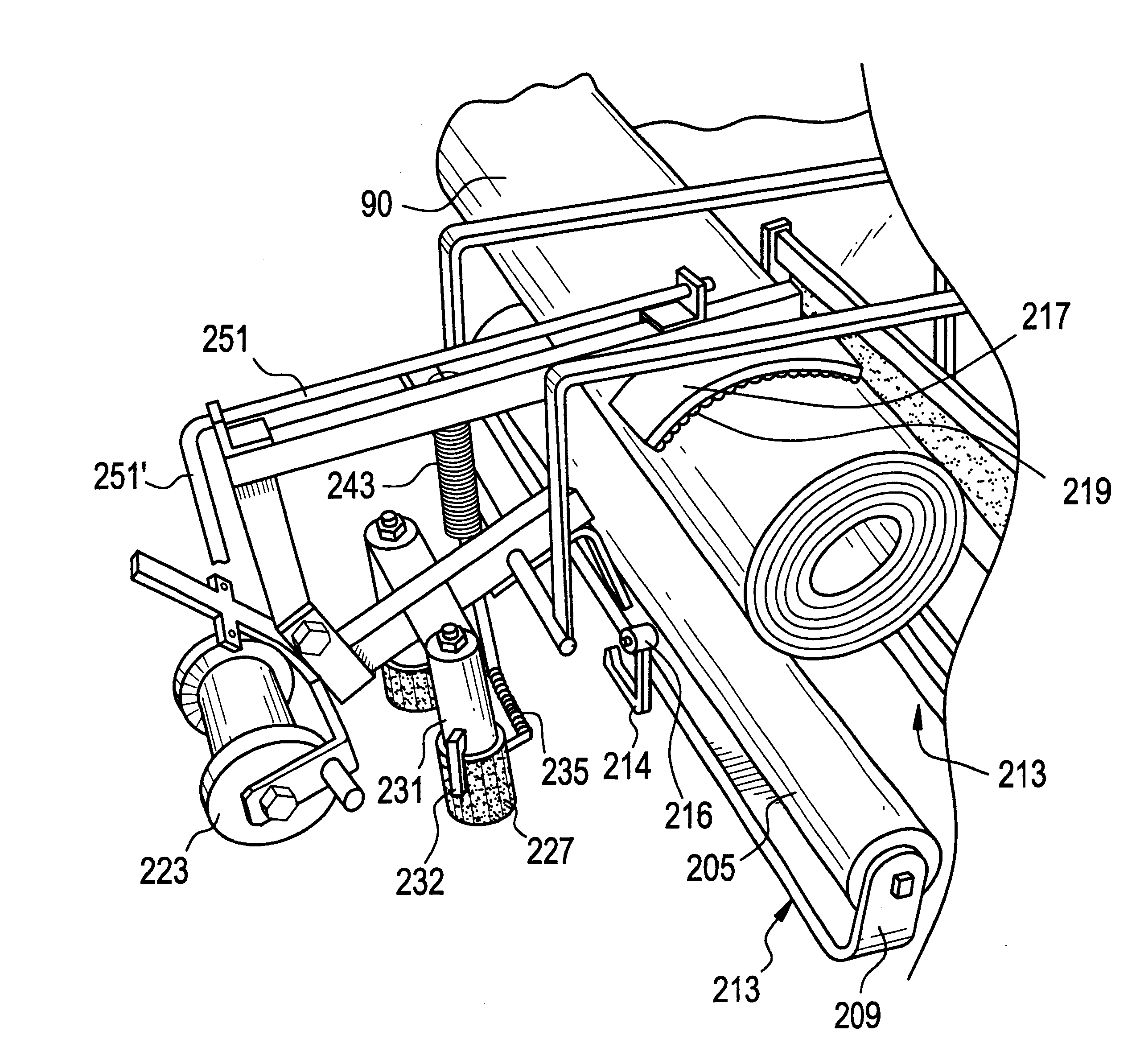
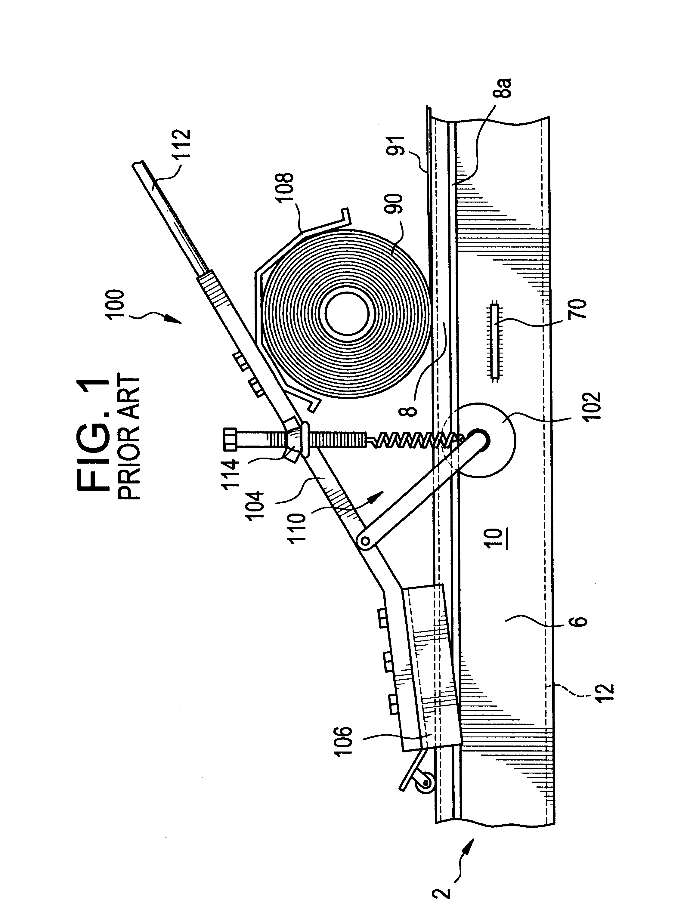
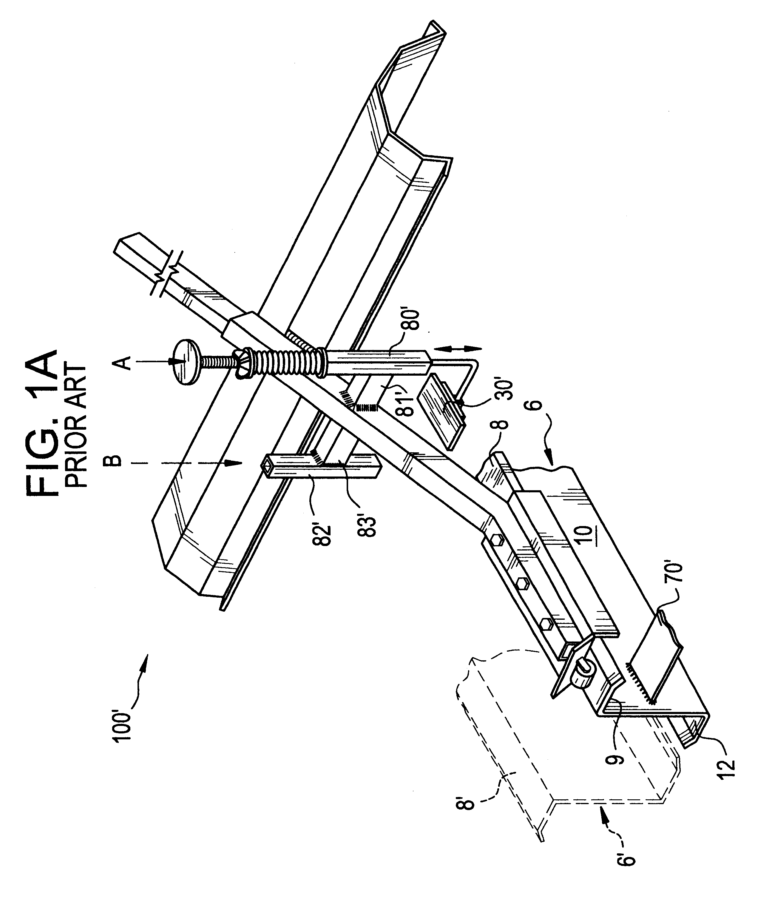
FIGS. 1, 1A and 2 (prior art) illustrate two known and rather successfully used, commercial dispensers 100 and 100' for applying a roll of fabric 90, such as high-density, woven-polyethylene, over purlins in a roof system. Generally speaking, commercial dispenser 100 includes frame member 104, guide 106 for embracing the top flange of a purlin (or girt) 6 with a minimum amount of friction, and fabric roll retaining means 108 for retaining a roll of fabric 90 against the surface of the flanges of purlins 6. Provided as a means for biasing the roll against the purlin flanges onto which the sheet 91 of fabric is applied (with or without adhesive or adhesive tape first being applied) is tensioning device 110. Through its biasing spring, adjustable by wing nut 114, the entire device 100 is secured to the upper surface of the purlin flange via a glide roller 102, upwardly biased by the coil spring against the undersurface of the flange. For convenience, only purlin 6 and cross support mem...


PUM


Abstract

Apparatus for dispensing a rolled fabric across the width of at least two longitudinal structural supports. In some embodiments, apparatus which is capable of forming a fall protection system which conforms to OSHA standards when constructing metal insulated roof systems.

Description

This invention relates to apparatus for dispensing a rolled fabric across the width of at least two longitudinal structural supports and, in particular embodiments, to apparatus capable of forming a fall protection system which conforms to OSHA standards when constructing metal insulated roof systems.Metal roof structures are typically comprised of a series of rafters which extend parallel to each other from each side of a building to its roof peak. Longitudinal structural supports (eg. purlins or bar joists) are typically mounted on top of and perpendicular to these rafters in a similarly parallel fashion.In one manner of constructing such a known metal roof structure as described, a fabric (eg. polyethylene) is first rolled in sheets over these purlins. These sheets then serve as a vapor barrier for the metal roof structure. Once the insulation is installed over the sheet of fabric, the insulation is secured in place with hard (typically metal) roof sheeting attached to the upper ...

Claims


Application Information

Patent Timeline
Patent Type & Authority Patents(United States)
IPC IPC(8): B65H23/08B65H23/06B65H18/14B65H16/00B65H18/20B65H16/08B65H77/00
CPCB65H16/08B65H18/20B65H23/08E04D15/06B65H2701/1922
Inventor ROMES, GARY E.
Owner SILVERCOTE
Why Eureka
Try Eureka