

Method and apparatus for applying a material to a web
a technology of material and web, applied in the field of method and apparatus for applying a material to a web, can solve the problems of repetitive application of additional material bands to the web, unworkable apparatus at the wet end of paper-making machines, etc., and achieve the effect of increasing the add-on weight, reducing the number of slots, and reducing the number of additional materials
Inactive Publication Date: 2003-07-22
PHILIP MORRIS USA INC
View PDF9 Cites 84 Cited by
- Summary
- Abstract
- Description
- Claims
- Application Information
AI Technical Summary
Problems solved by technology
Additionally, such apparatus are unworkable at the wet-end of paper-making machines.
As a result, bands of additional material are applied repetitively to the web.
Method used
View moreImage
Smart ImageViewing Examples

Examples
example ii
A high speed trial was conducted using the following three slotted belt designs wherein the slots were oriented at 45.degree. to the travel direction of the belt:
As a result of the test, it was determined that as slot width decreases (e.g., from 2 / 32 inch to 1 / 32 inch), the width of the resulting bands also decreases.
Login to View More PUM
| Property | Measurement | Unit |
|---|---|---|
| width | aaaaa | aaaaa |
| diameter | aaaaa | aaaaa |
| thickness | aaaaa | aaaaa |
Abstract
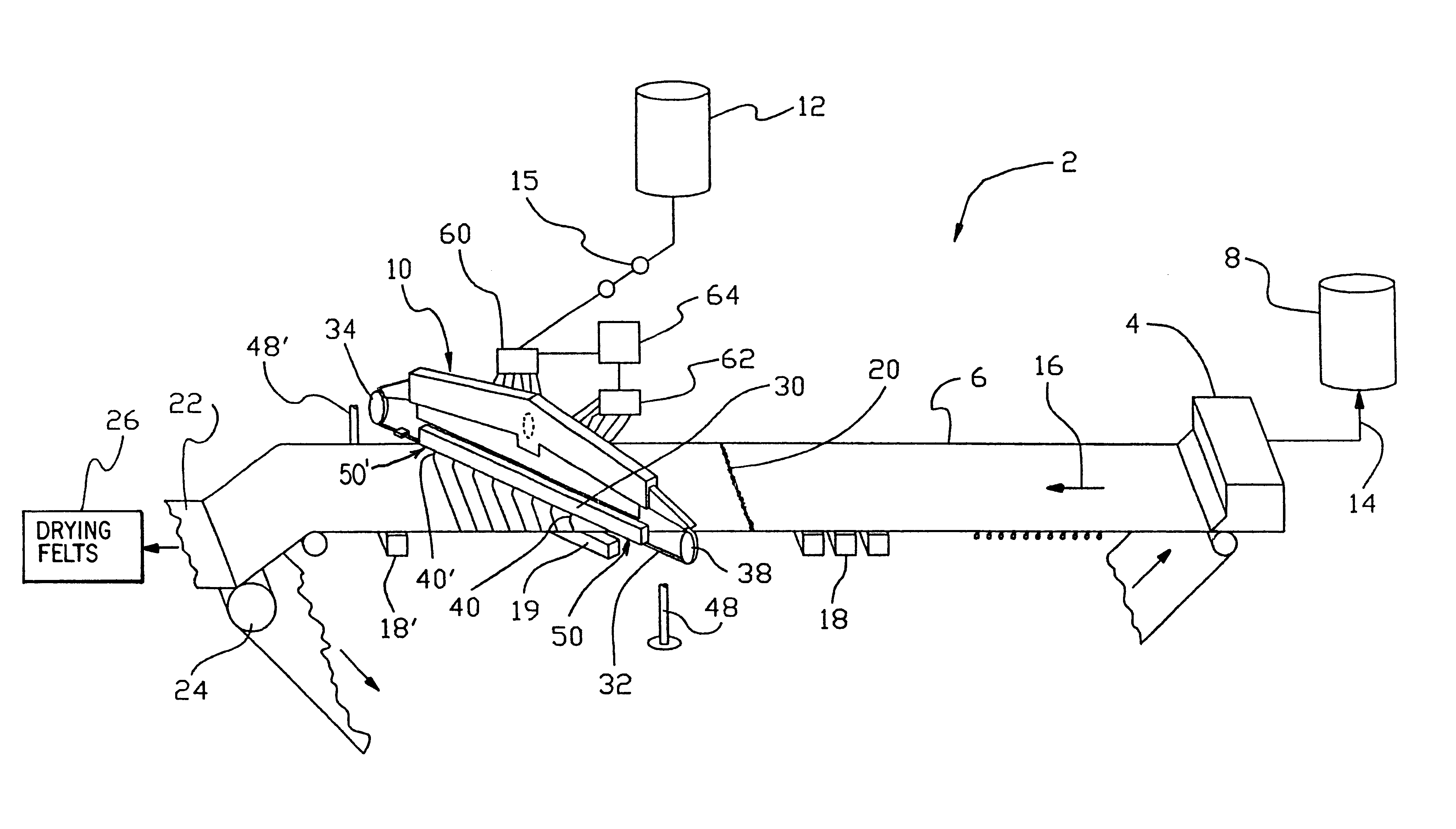
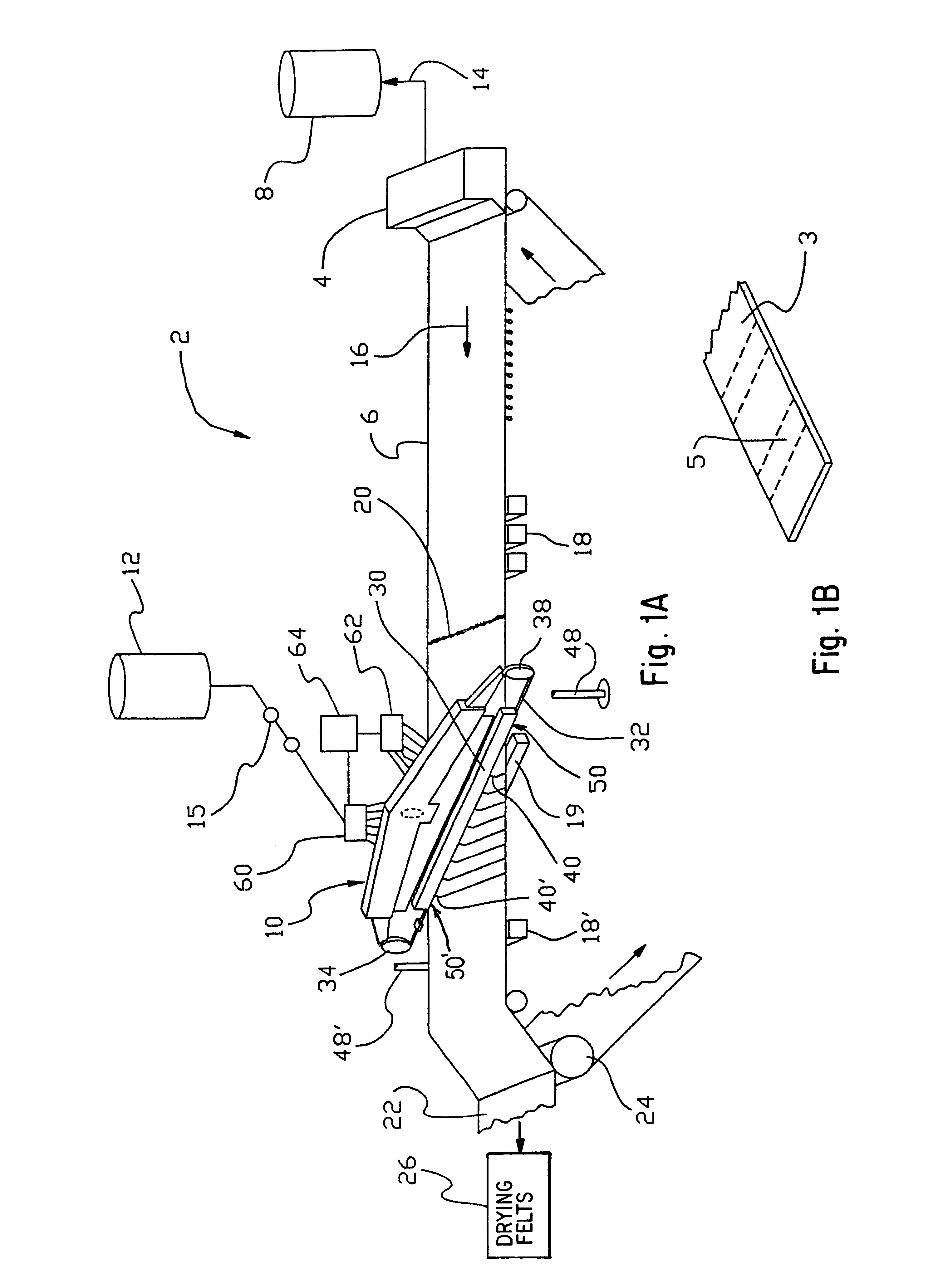
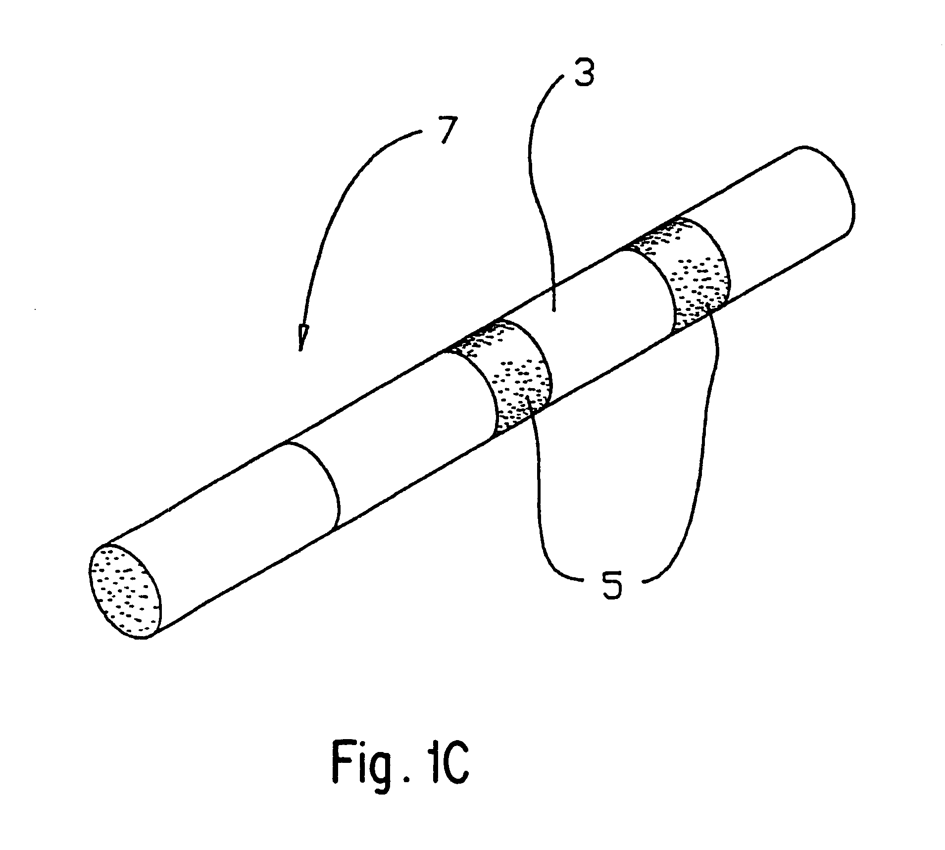
A method and apparatus of manufacturing a web which is striped with add-on material, comprising: a first slurry supply which forms a sheet of base web and moves the sheet along a first path; a second slurry supply; and a moving orifice applicator operative so as to repetitively discharge the second slurry upon the moving sheet of base web. The moving orifice applicator includes a chamber box arranged to establish a reservoir of the second slurry across the first path, an endless belt having slotted orifices, the endless belt received through the chamber box, and a drive arrangement operative upon the endless belt to continuously move the orifices along an endless-path and repetitively through the chamber box. The orifices communicate with the reservoir to discharge the second slurry as bands of add-on material to the base web. The slotted orifices can be spaced apart along the belt and oriented so as to be angled with respect to the travel direction of the belt and parallel to each other.
Description
The present invention relates to method and apparatus for applying a predetermined pattern of add-on material to a base web, preferably in the form of stripes, and more particularly, to a method and apparatus for producing cigarettes papers having banded regions of additional material.BACKGROUND AND CIRCUMSTANCES OF INVENTIONTechniques have been developed for printing or coating paper webs with patterns of additional material. These prior techniques have included printing with gravure presses, blade coating, roller coating, silkscreening and stenciling.U.S. Pat. No. 4,968,534 to Bogardy describes a stenciling apparatus wherein a continuous stencil comes into intimate contact with a paper web during application of an ink or the like. The apparatus includes an arrangement which draws air through the stencil prior to the application of the ink. The mechanical arrangement is such that to change the pattern, the stencil must be changed. Additionally, such apparatus are unworkable at the ...
Claims
Login to View More Application Information
Patent Timeline
 Patent Type & AuthorityPatents(United States)
IPC IPC(8): B05C5/02D21H27/00D21H27/02
CPCB05C5/025B05C5/027
InventorGARG, RAJESHPHAN, TONY
OwnerPHILIP MORRIS USA INC