
Printing control apparatus, printing control method, printing control system, and storage medium in which printing control program is stored

a printing control and control system technology, applied in the direction of digital output to print units, instruments, digitally marking record carriers, etc., can solve the problems of affecting real-time performance, unable to quickly execute/manage another subsequent print job, and unable to perform job management before pdl data is interpreted

Inactive Publication Date: 2003-07-29
CANON KK
View PDF14 Cites 160 Cited by
  • Summary
  • Abstract
  • Description
  • Claims
  • Application Information

AI Technical Summary

Benefits of technology

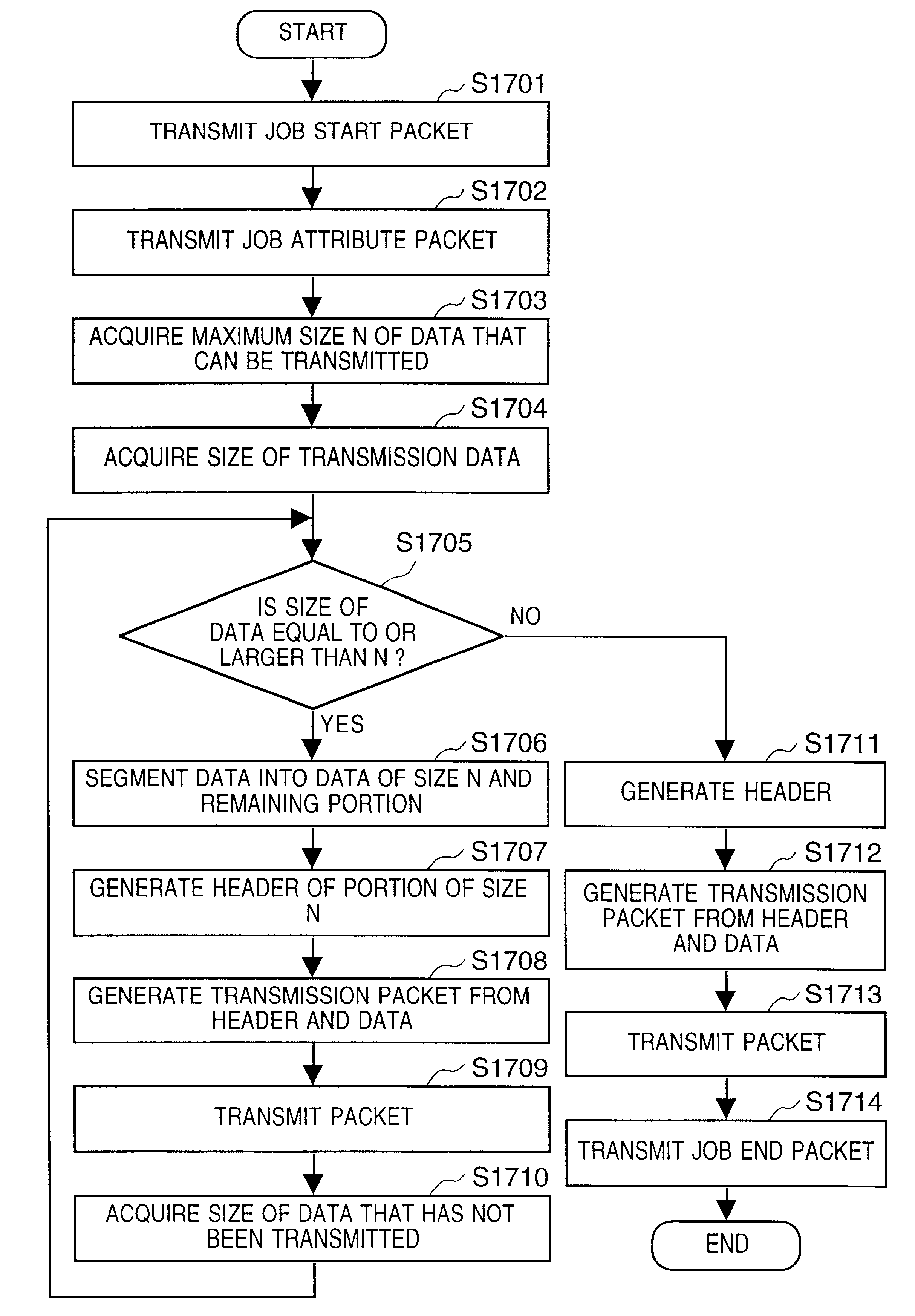
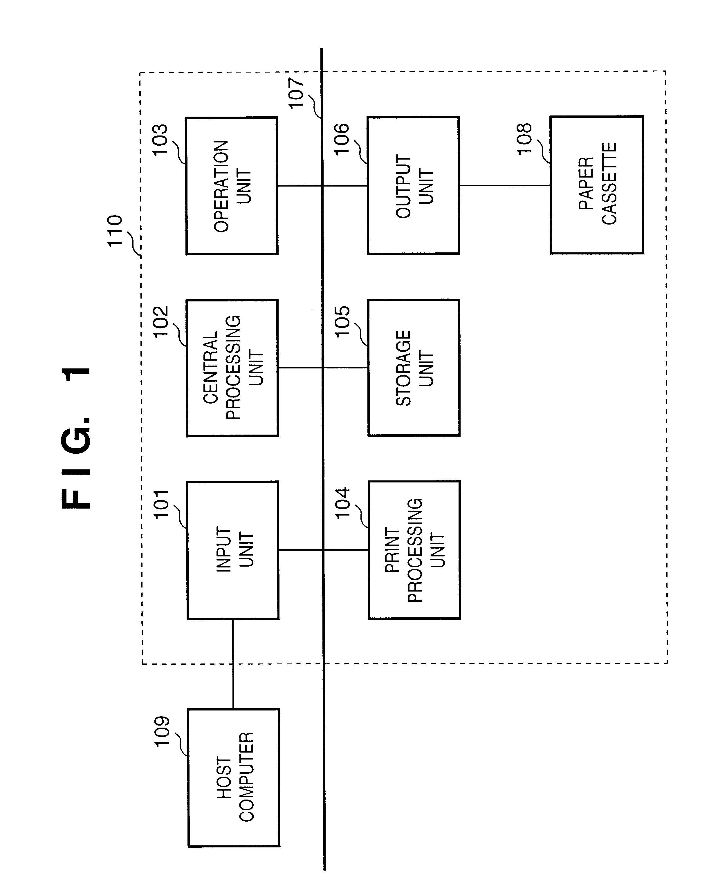
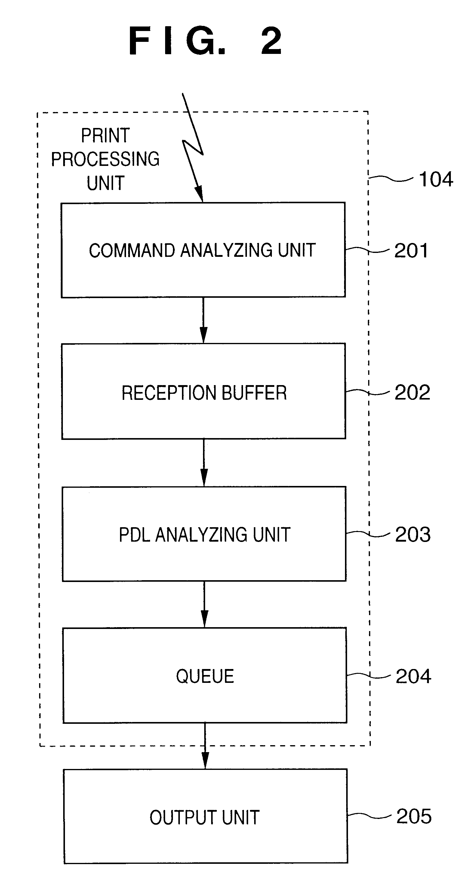
The present invention has been made in consideration of the above situation, and has as its object to provide a printing control apparatus which brackets or delimits data received by peripheral devices such as a printing apparatus by command information as in the prior art, and can recognize a job by only analyzing command information without interpreting the entire PDL data to be output by storing the command information itself or the data size following the command information in the command information, and includes a command print processing unit for analyzing the command information upon reception of data and a means for holding the job information analyzed by the command print processing unit, thereby allowing management / control of jobs on a sequence of processing immediately after data reception or following data reception, a printing control method, a storage medium storing a printing control program, and a printing control system.

Problems solved by technology

If, therefore, it takes much time to analyze a print job in the print processing unit 504, another subsequent print job cannot be quickly executed / managed.
The following three problems are, however, posed in print processing performed in units of print jobs by using the JL as in the prior art.
Job management cannot be performed before PDL data is interpreted.
This impairs the real-time performance.
Also, since the execution of print processing depends on the state of preceding print processing, the output timing and the like of a subsequent print job is unknown, requiring an excess wait time.
This shortens the processing time.

Method used


Image

  • Printing control apparatus, printing control method, printing control system, and storage medium in which printing control program is stored
  • Printing control apparatus, printing control method, printing control system, and storage medium in which printing control program is stored
  • Printing control apparatus, printing control method, printing control system, and storage medium in which printing control program is stored

Examples


second embodiment

In the second embodiment of the present invention, control operation is performed to change the processing order of data added to a queue in accordance with user's intention by using the system of the first embodiment described above. This control operation will be described below.

When priority information set by a user with a printer driver unit 1502 of a host computer 109 is stored in a transmission buffer 1503, together with PDL data, a job packet generating unit 1507 adds the priority information indicating the priority levels of jobs to the parameter information in a job packet, and transmits the job packet to a printing apparatus 110. The printing apparatus 110 transfers the received print job to a queue 204, re-assigns a queue number 402 to the job, and processes the job in accordance with the designated priority. The priority levels are expressed by the priority information transmitted from the host computer 109 like "1, 2, 3, . . . " or "A, B, C, . . . ".

When jobs are to be...


PUM


Abstract

A printing control apparatus for analyzing and processing an input print job that includes printing management data for managing the print job and print data. Header information identifying the printing management data has been added to the printing management data and header information identifying the print data and indicating a data size of the print data has been added to the print data. Header information of input data is analyzed and input data determined to be printing management data in accordance with the header information is stored in a management information storage medium and input data determined to be print data in accordance with the head information is stored in a print data storage medium on the basis of the data size indicated in the header information, without analyzing the print data.

Description

1. Field of the InventionThe present invention relates to a printing control apparatus for controlling to print out a print job transmitted from a host computer and, more particularly, to a printing control apparatus for analyzing and printing print jobs, each having a data size as additional information, in units of commands, when data is exchanged between a client and a host, a printing control method, a storage medium in which a printing control program is stored, and a printing control system.2. Description of the Prior ArtThe prior art will be described with reference to FIGS. 5 and 6. FIG. 5 shows the arrangement of a printing apparatus. FIG. 6 is a flow chart showing the operation of the prior art which is to be performed upon reception of data from a host computer.Referring to FIG. 5, reference numeral 501 denotes a printing apparatus main body; 502, a host computer (host) for sending data to the printing apparatus main body 501; 503, a input unit for receiving the data sent...

Claims


Application Information

Patent Timeline
Patent Type & Authority Patents(United States)
IPC IPC(8): G06F3/12B41J29/38
CPCG06F3/1296G06F3/1285G06F3/1212G06F3/1263
Inventor OSADA, MAMORUSHIMOTAI, NAOKO
Owner CANON KK
Learn More