Motor bogie for a vehicle having an integral low-slung floor

a technology of low-slung floor and motor bogie, which is applied in the direction of locomotive transmission, axle box mounting, electric motor propulsion transmission, etc., can solve the problems of occupying the space between the insides of the wheels, limiting the width of the floor at the bogies, and displacing the floor

Inactive Publication Date: 2003-08-05
ALSTOM TRANSPORT TECH SAS
View PDF14 Cites 23 Cited by
  • Summary
  • Abstract
  • Description
  • Claims
  • Application Information

AI Technical Summary

Benefits of technology

An object of the present invention is thus to remedy the various drawbacks by proposing a motor bogie for a rail vehicle having an integral low-slung floor that makes it possible to have a floor at the bogie that extends at very low height over a width close to the spacing between the wheels. Another object of the present invention is to propose a motor bogie for a rail vehicle that has braking members that are easily accessible and that can be fitted interchangeably both to carrying bogies and to motor bogies.

Problems solved by technology

Unfortunately, such a bogie suffers from the drawback of having axles and axle boxes that occupy the space between the wheels, and thus make it necessary to dispose the floor above the axles.
Such a bogie offers the advantage of not having any axle shaft links between the individual wheels, thereby making it possible to lower the floor further, but unfortunately, it suffers from the drawback of including wheel shafts that are guided by axle boxes disposed on the insides of the wheels, thereby occupying the space between the insides of the wheels and limiting the width available for the floor at the bogies.
Such a bogie also suffers from the drawback of including braking members which are associated with the gearing and which are thus specific to a motor bogie, and the rail vehicle thus has braking members that are different on the motor bogies than on carrying bogies, thereby complicating maintenance operations.

Method used


Image

  • Motor bogie for a vehicle having an integral low-slung floor
  • Motor bogie for a vehicle having an integral low-slung floor
  • Motor bogie for a vehicle having an integral low-slung floor

Examples


Embodiment Construction

To make the drawings more legible, only those elements which are necessary to understand the invention are shown. Like elements are given like references from one figure to the other.

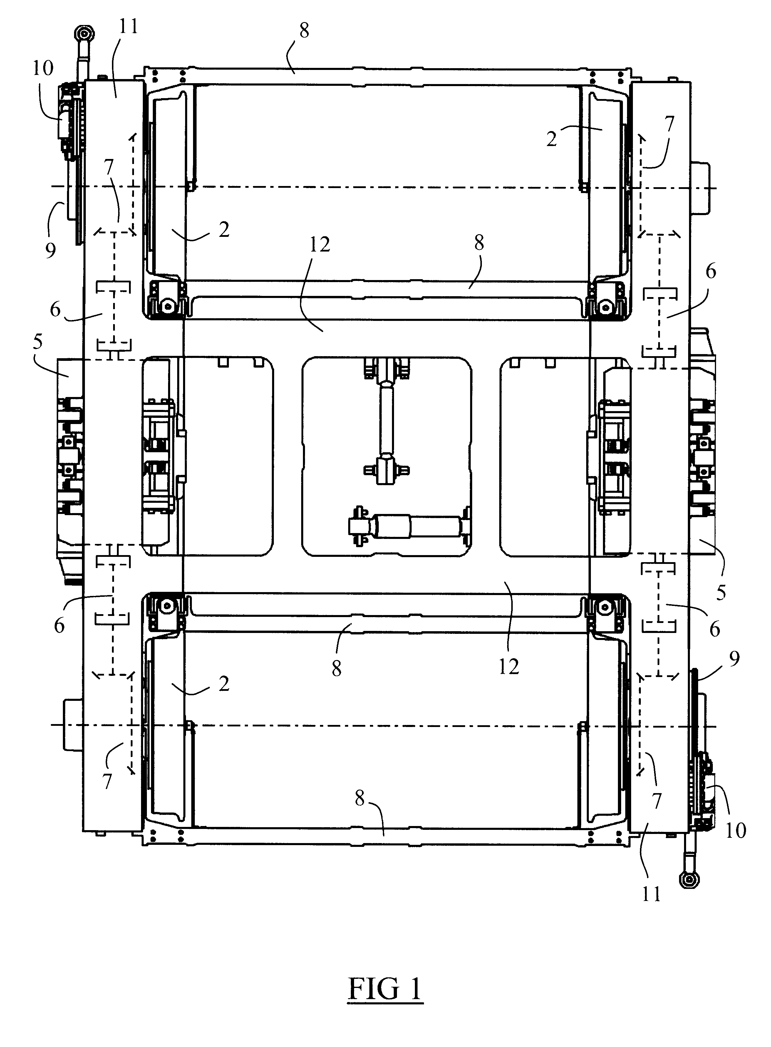
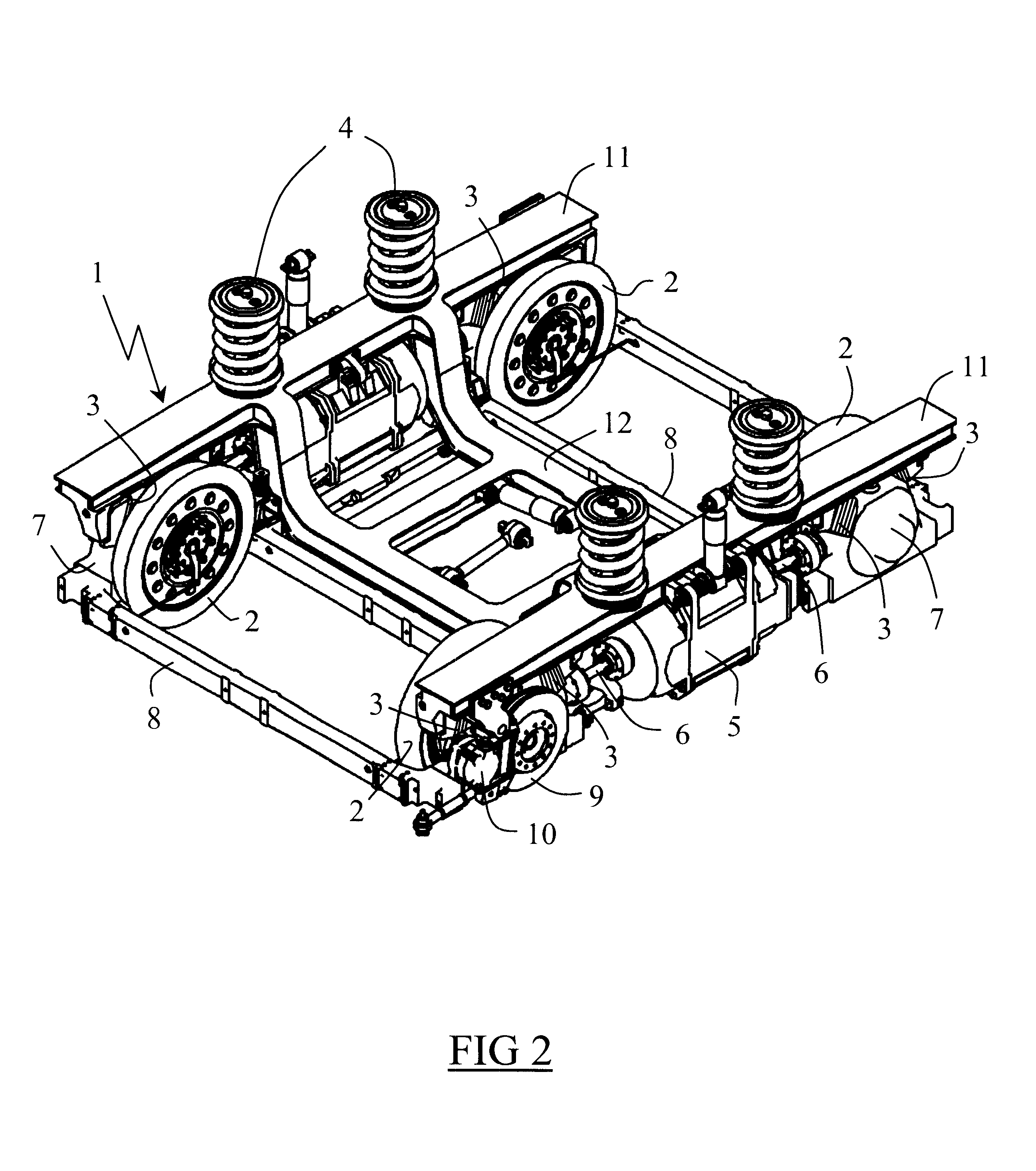
FIGS. 1 and 2 show a tram bogie having a frame 1 resting on four wheels 2 via a primary suspension 3 allowing vertical displacement of about .+-.15 mm. The four wheels 2 are distributed conventionally over two sets of wheels, each set serving to come onto a respective rail of the track, each of the wheels 2 having an individual wheel shaft mounted on an axle box and the wheels not being interconnected via axle shafts.

As shown in FIG. 2, the frame 1 comprises a structure made up mainly of two longitudinal sole-bars 11 interconnected via two cross-members 12, the longitudinal sole-bars 11 being disposed outside the wheels 2 and extending at a height higher than the axes of the wheels 2. The cross-members 12 extend perpendicularly to the longitudinal sole-bars 11, and each of them has a low central portion...


PUM


Abstract

A motor bogie for a rail vehicle having an integral low-slung floor, the motor bogie having a frame resting on four wheels via a primary suspension, the frame supporting at least one motor disposed on one side of the frame and connected to at least one wheel via transmission, wherein each wheel has an individual wheel shaft supported by an axle box, and wherein the transmission comprise a gear unit coupled directly to the shaft of the wheel and a telescopic transmission of the type having a double universal joint and disposed between the gear unit and the motor, the gear unit being placed outside the wheel, and having a casing incorporating the axle box of the shaft of the wheel, the casing of the gear unit serving as a support element for supporting a primary suspension member on which the frame bears.

Description

The invention relates to a motor bogie for a rail vehicle having an integral low-slung floor, and more particularly to a bogie having a frame resting on four wheels via a primary suspension, the frame supporting at least one motor disposed on one side of the frame and connected to at least one wheel via transmission means.The invention is suitable in particular for trams in which a low-slung floor facilitates access (both when boarding and when alighting) for children, old people, and the disabled.The Applicant's Patent Application FR 2 637 861 discloses a motor bogie for a rail vehicle having a low-slung floor. That bogie has a frame resting on two axles via a primary suspension, the frame supporting traction motors disposed on the sides of the bogie and connected to the wheels via transmission means disposed outside the wheels. Unfortunately, such a bogie suffers from the drawback of having axles and axle boxes that occupy the space between the wheels, and thus make it necessary t...

Claims


Application Information

Patent Timeline
Patent Type & Authority Patents(United States)
IPC IPC(8): B61C9/52B61C9/00B61F3/00B61F3/16B61C9/38B61F5/30B61F5/52B61H5/00
CPCB61C9/52B61F3/16
Inventor ECHE, CHRISTOPHELOISEAU, JEAN-CHRISTOPHERODET, ALAIN
Owner ALSTOM TRANSPORT TECH SAS
Why Eureka
Try Eureka