Driving unit of a welding equipment

a driving unit and welding equipment technology, applied in the direction of manufacturing tools, resistance electrode holders, gearing, etc., can solve the problems of unstable operation, long driving unit length, complex driving unit,

Inactive Publication Date: 2003-08-05
OBARA GRP
View PDF17 Cites 62 Cited by
  • Summary
  • Abstract
  • Description
  • Claims
  • Application Information

AI Technical Summary

Problems solved by technology

However, in the first prior art, since the screw shaft is provided on the output shaft extended from the motor by way of a gear, a driving unit becomes complex and it becomes long in its entire length, resulting in a drawback of unstable operation when operating a motor-operated welding equipment.

Method used


Image

  • Driving unit of a welding equipment
  • Driving unit of a welding equipment
  • Driving unit of a welding equipment

Examples


first embodiment (fig.1)

First Embodiment (FIG. 1):

A driving unit of a welding equipment according to a first embodiment is described next.

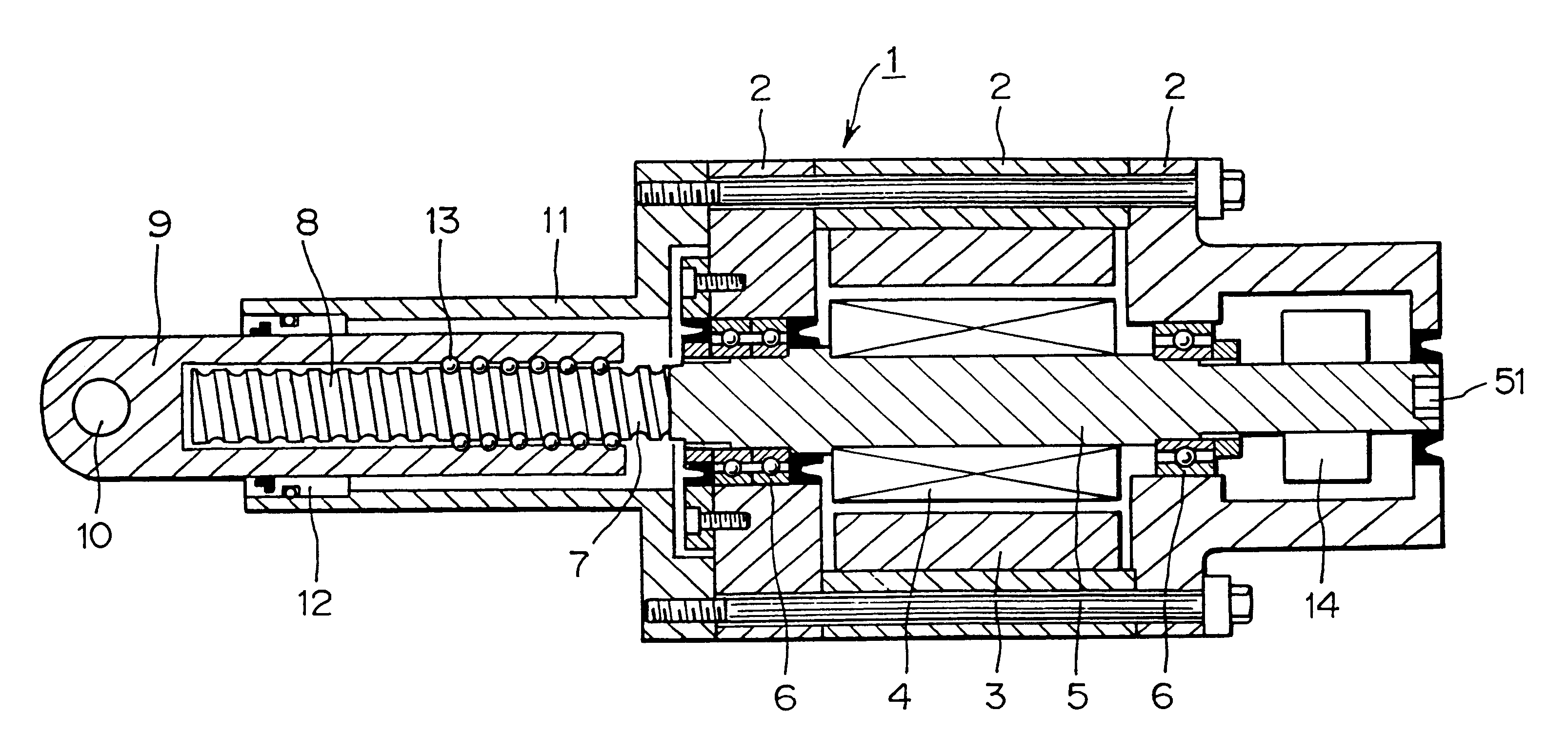
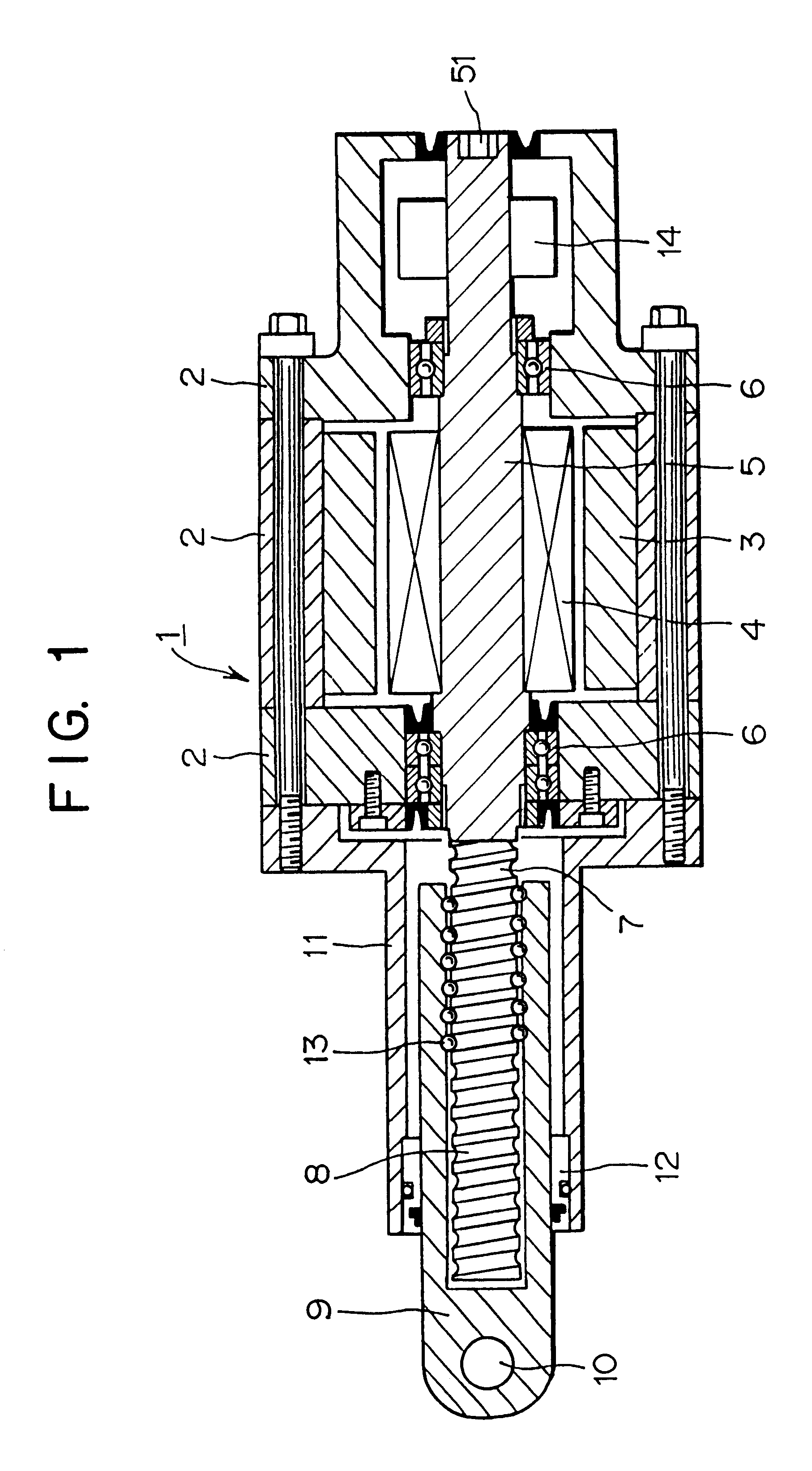
In FIG. 1, a servomotor 1 comprises a winding 3 of a stator that is fixed to an outer shell 2, a rotor magnetic pole 4 disposed at the inner periphery of the winding 3, and a rotary shaft 5 to which the rotor magnetic pole 4 is fixed, wherein the rotary shaft 5 is journaled by bearings 6 and supported by the outer shell 2 of the servomotor. The rotary shaft 5 is extended toward its output direction and the extended portion constructs a screw shaft 7 on which a male screw 8 is provided to form a ball screw. A machining part 51 to which a manually operating handle is mounted is formed on the end of the rotary shaft 5 opposite to the output side of the rotary shaft 5.

A pressure application shaft 9 is connected, e.g., to a movable arm (not shown) or swingable arm (not shown) by way of a trunnion shaft 10, or, e.g., to a workpiece placing table (not shown) at the front end th...

second embodiment (fig.2)

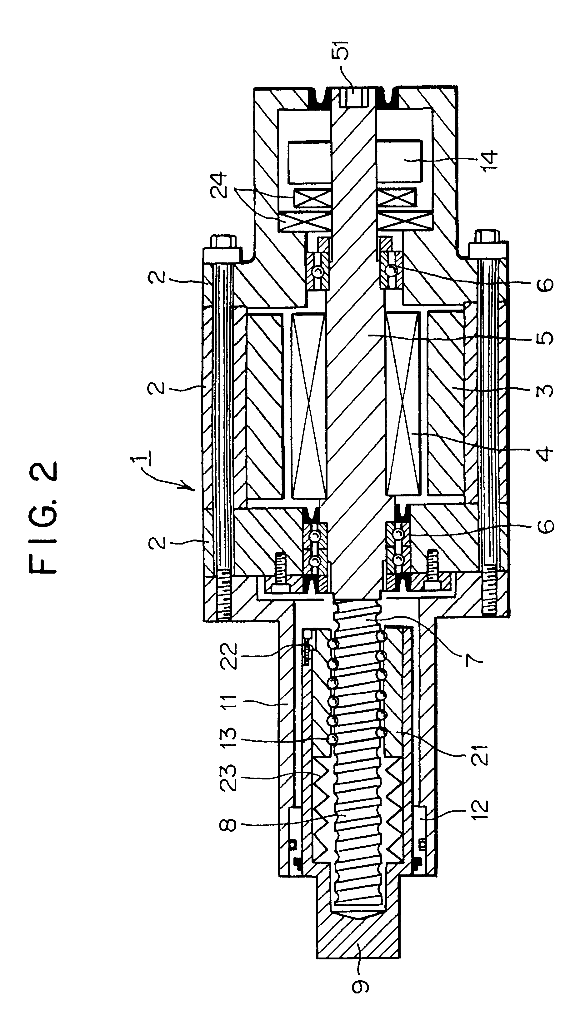
Second Embodiment (FIG. 2):

A driving unit of a welding equipment according to a second embodiment is described next.

A ball nut 21 on which a female screw 13 is provided is slidably disposed relative to a pressure application shaft 9 wherein the ball nut 21 is integrally provided on the pressure application shaft 9 by way of a baffling member 22 so that the former is not turned relative to the latter. A conical spring 23 formed of an elastic body is disposed between the tip end of the ball nut 21 and the pressure application shaft 9. A position detector 14 and a electromagnetic brake 24 are disposed on a rotary shaft 5.

Other components of the driving unit of a welding equipment are substantially the same as those of the first embodiment, and hence they are depicted by the same reference numerals and the explanation thereof is omitted.

Although a screw shaft 7 is turned as a servomotor 1 turns, the ball nut 21 is advanced relative to the pressure application shaft 9 while it is slid by...

third embodiment (fig.3)

Third Embodiment (FIG. 3):

A driving unit of a welding equipment according to a third embodiment is described next.

A hole 31 through which a screw shaft 7 is inserted is bored in a rotary shaft 5 of a servomotor 1. A power lock mechanism 32 formed by utilizing a wedging operation by an inner ring and an outer ring is disposed between the screw shaft 7 and the rotary shaft 5 so as to fix the rotary shaft 5 to the screw shaft 7. Accordingly, the screw shaft 7 and rotary shaft 5 are commonly journaled by common bearings 6. A nut 33 meshing with the male screw 8 formed on the screw shaft 7 is integrally fixed to the inner periphery of the pressure application shaft 9 at the end thereof.

Other components of the driving unit of a welding equipment are substantially the same of those of the first embodiment, and hence they are depicted by the same reference numerals and the explanation thereof is omitted.

In the third embodiment, the screw shaft 7 is turned as the servomotor 1 turns so that t...


PUM

PropertyMeasurementUnit
forceaaaaaaaaaa
rotary forceaaaaaaaaaa
outer diameteraaaaaaaaaa

Abstract

There is provided a driving unit of a welding equipment capable of reducing the size of the driving unit, of reducing the moment of inertia, and of being compact and having an excellent operability. The driving unit of a welding equipment provided with a pressure application shaft that is driven by a motor comprises a screw shaft provided integrally with or substantially integrally with a rotary shaft of the motor, a nut provided integrally with or substantially integrally with the pressure application shaft and is screwed with a screw of the screw shaft, and a baffling mechanism provided on the pressure application shaft, and wherein the rotary shaft of the motor is positioned substantially coaxially with the screw shaft and a rotary force outputted from the rotary shaft of the motor is converted into a reciprocating motion of the pressure application shaft.

Description

1. Field of the InventionThe invention relates to a driving unit of a welding equipment capable of converting a rotary output of a motor into reciprocating motion of a pressure application shaft so that the pressure application shaft can operate a gun arm or a welding jig.2. Related ArtThere is a known driving unit of a welding equipment provided with a pressure application shaft to be driven by a motor as disclosed, for example, in Japanese Utility Model Registration No. 3042268 and Patent Laid-Open Publication No. 9-144834, wherein a screw shaft is provided on an output shaft extended from a motor by way of a gear and a screw provided on one end of the screw shaft is screwed with a nut formed on the pressure application shaft (hereinafter referred to as a first prior art).There is a further known driving unit of a welding equipment provided with a pressure application shaft to be driven by a motor as disclosed, for example, in Japanese Patent Laid-Open Publication No. 7-290251, wh...

Claims


Application Information

Patent Timeline
Patent Type & Authority Patents(United States)
IPC IPC(8): B23K11/31B23K11/30F16H25/20H02K7/06B23K11/11
CPCB23K11/31B23K11/315B23K11/318F16H25/20H02K7/06F16H25/2204F16H2025/2065F16H2025/2075B23K11/11
Inventor SATO, YOSHIO
Owner OBARA GRP
Why Eureka
Try Eureka