Automatic framing camera

a camera and automatic technology, applied in the field of automatic framing cameras, can solve the problems of not being able to apply the same effect to still subjects, not being able to meet the needs of low-cost systems, and requiring a large amount of time until the human area, so as to achieve low pixel count, shorten image processing time, and low cost

Inactive Publication Date: 2003-08-12
NISCA KK
View PDF7 Cites 36 Cited by
  • Summary
  • Abstract
  • Description
  • Claims
  • Application Information

AI Technical Summary

Benefits of technology

According to the above, a still subject has its ranging direction changed by a direction changing means and is identified from changes in the ranging information by the ranging means, and the photographing direction of the photographing means is turned toward the subject by the direction changing means and the subject is photographed, so it is possible to obtain an image of a still subject while also having the subject framed in the obtained image, and because image processing such as cutting out images for framing is not necessary, it is possible to make the system higher speed and lower cost.
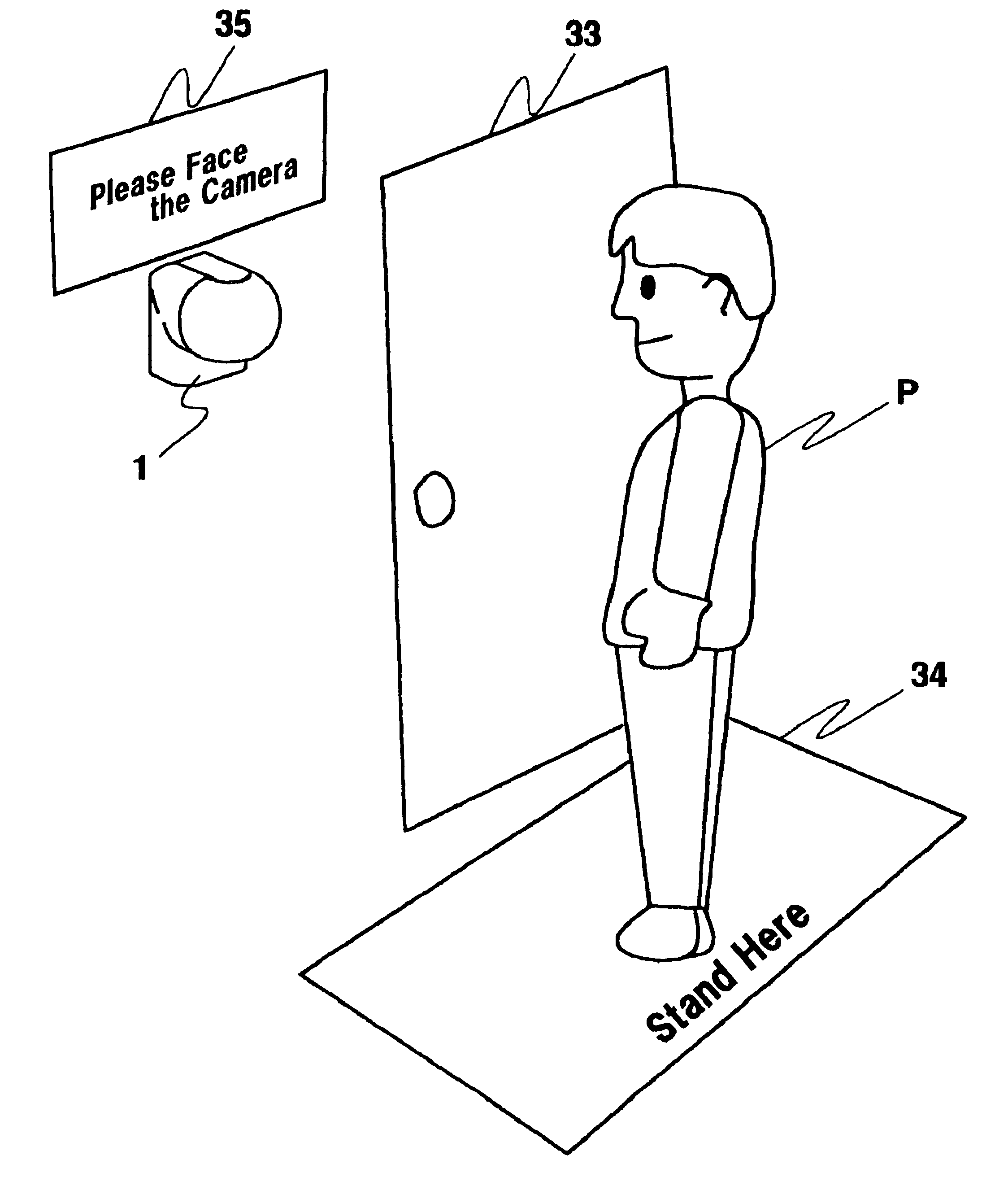
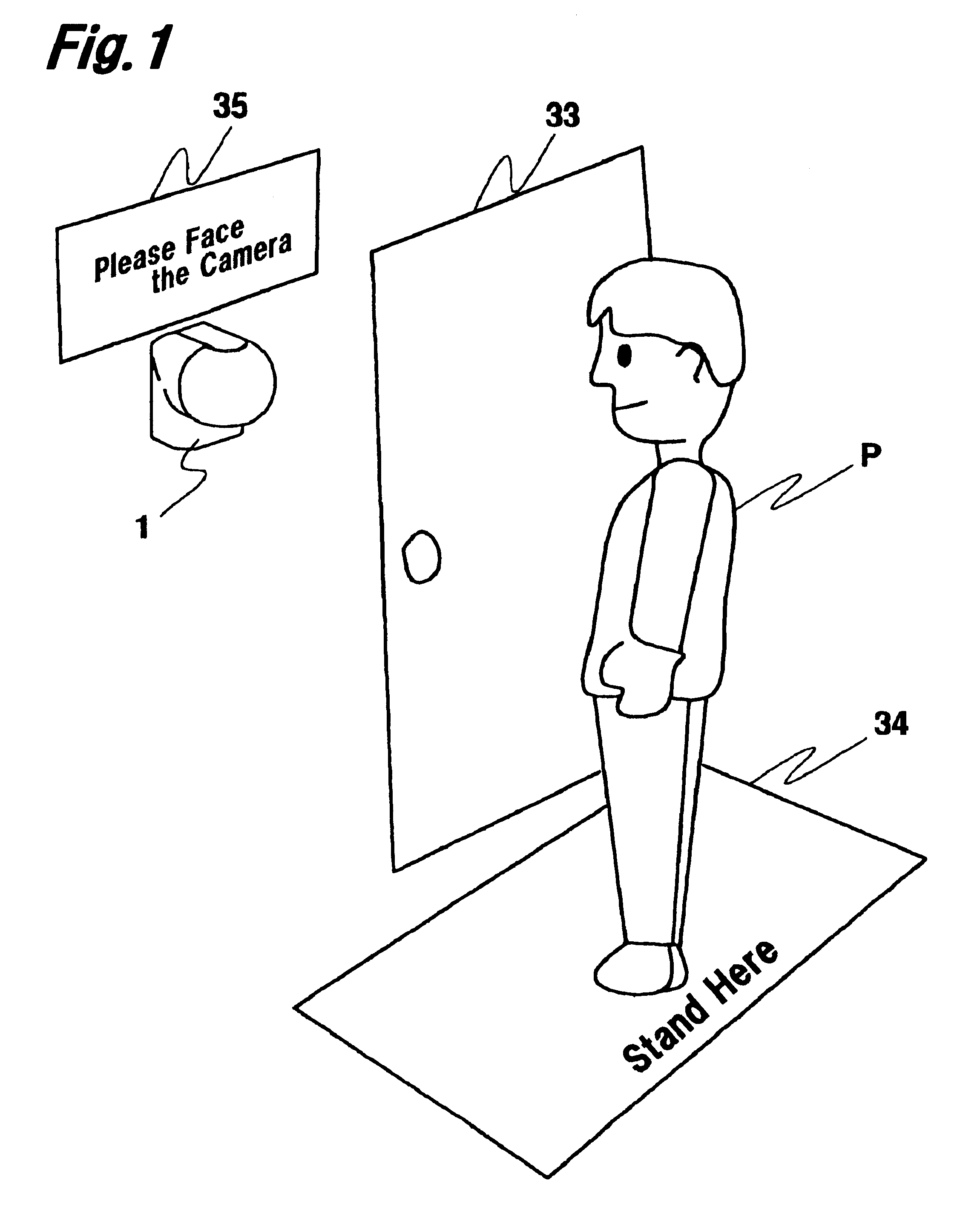
With camera 1 of this embodiment, the ranging direction D of the ranging unit (light emitting element 5 and light receiving element 6) that is capable of ranging in one direction by pan motor 13 and tilt motor 12 is changed (steps 108 to 116), and still person P is identified by changes in signals from the ranging unit by control circuit 20 (steps 118 to 122). Then, the photographing direction D of photographic lens 3 is turned by tilt motor 12 toward face center P.sub.E of the identified person P, face center P.sub.E of person P is framed in the center of angle of view V.sub.A (steps 124 to 138), and the face of person P is photographed by imaging element 4. Therefore, with camera 1 of this embodiment, it is possible to obtain an image of the face of still person P, so at the host unit, since it is not necessary to do trimming processing of cutting the face part of person P from the background, etc. as was required with the prior art, it is possible to shorten the image processing time and at the same time, to use a low pixel count, low cost camera because the high resolution conversion of imaging element 4 that occurs with trimming processing is not necessary. In other words, by using camera 1 of this embodiment, there is no need for trimming processing which focuses on the face of person P after fetching the image, and it is possible to obtain a post trimming process image at the point the image is fetched, so it is possible to shorten the processing time at the host unit and to lower the cost of the camera.
Also, almost all photographic subjects (persons P) are in the position closest to camera 1, so with this embodiment, even when there are multiple subjects including persons P and P', by photographing the face of person P who is the subject closest to camera 1 using imaging element 4, identification of the subject is simplified. Therefore, with this embodiment, we showed an example of operating micon 21 using software (a program), but it is also possible to form the control circuit using hardware that includes a comparator, etc. without using micon 21 or software, so it is possible to make the device lower in cost and smaller in size.
Furthermore, with camera 1 of this embodiment, an active method triangular ranging [device] is used. Because of this, by making light emitting element 5 emit light in the infrared range, it is possible to identify a subject such as a person P even in a dark place. Also, after identifying the center of the face of person P once, camera 1 of this embodiment makes infrared LED 14 emit light (step 140), and photographs the face of person P using imaging element 4, so there is no surprising the subject person P or damaging the vision of person P. Furthermore, with camera 1 of this embodiment, the structure is such that there is no IR cut filter in photographic lens 3, so imaging element 4 can photograph even in the infrared range. Specifically, a camera 1 for verification such as the one of this embodiment is typically placed in a relatively dark place such as a corridor or entryway, so the infrared range active method is used, light is projected on the subject by infrared LED 14, and by further using photographic lens 3 from which the IR cut filter has been removed, it is possible to exhibit the original functions of a verification camera which can take photographs even in dark places.
Even further, with camera 1 of this embodiment, a light emitting element 5 with a light spot diameter of about 3 mm was used. When the light spot diameter is too large, there are cases when it is difficult to distinguish the output from light receiving element 6, so that the outline, etc. of person P is unfocused. With camera 1 of this embodiment, we used a small diameter for which poor focus problems do not occur for the light spot of light emitting element 5, so it is possible to get an accurate grasp of the signal changes, and to frame the face of person P without error for photographing.

Problems solved by technology

However, with the technology of Tokkaihei 2001-43381, it is necessary to perform image processing that extracts the human area at high speed while capturing the image, and a high speed image processing function is required, so this is not suitable for low cost systems.
Also, depending on the performance of the image processing function, a good deal of time may be required until the human area is extracted.
Also with this technology, the method is to obtain the difference before and after moving, so it is difficult to apply this to still subjects.
Also, with the technology of Tokkaihei 9-289609, use is difficult on subjects that do not emit sound and in places where there is noise, such as outdoors.
Furthermore, this is not suitable for use as a means of accurately framing a person for photographing because of sound reflection problems and sound directivity accuracy problems using sound to detect detection.

Method used


Image

  • Automatic framing camera
  • Automatic framing camera
  • Automatic framing camera

Examples


embodiment

As described above, with camera 1 of this embodiment, tilt direction support axes 11 are provided on the same axis substantially horizontally, extending on the opposite side of imaging element 4 from the cylinder body outer periphery surface of light emitting element 5 and light receiving element 6. In fact, as shown in FIG. 8 (A), the axis position is arranged so as to extend from the center of gravity position in relation to all materials (including control circuit 20, etc.) fixed to third frame 9. Note that FIG. 8 shows a typical example of the vicinity of third frame 9 shown in FIG. 3, and that since light emitting element 5 and light receiving element 6 do not have the same weight, light emitting element 5 is shown larger to make it easier to see this weight difference.


PUM


Abstract

This invention provides an automatic framing camera that identifies a still subject, frames it, and photographs it.The ranging direction of a ranging unit (light emitting element and light receiving element) that can range in one direction is changed by a pan motor and a tilt motor, and a still person is searched for by changes in the signal from the ranging unit. Then, the photography direction of the imaging element is turned by the tilt motor toward the center of the face of the person that was found, this is framed with the center of the person's face in the center of the angle of view, and the person's face is photographed by the imagining component.

Description

1. Technical FieldThe present invention relates to an automatic framing camera comprising a framing means for detecting the position of a still subject, and of automatically framing this within a photographic range.2. Prior ArtIn recent years, progress has been made in development of systems such as verification systems that photograph a person's face and convert this to an electronic image, automatically identify that person from this image information, and verify the person as the actual person making an application, and in development of recognition systems that automatically recognize special features of an object. With these systems, if there is a large volume of information for the image information required for verification or recognition, it is possible to prevent an erroneous judgment, so it is necessary to have an image that frames a full photographic image of a person's face or the special features of an object. To do this framing automatically, it is necessary to aim the...

Claims


Application Information

Patent Timeline
Patent Type & Authority Patents(United States)
IPC IPC(8): G03B13/18
CPCG03B13/18H04N5/2259H04N23/58
Inventor UMEDA, YOSHIHITOKASAI, MOTOKIMASUYAMA, KENJI
Owner NISCA KK
Why Eureka
Try Eureka