
Guide plate, surface light source device and liquid crystal display

a technology of light guide plate and surface light source device, which is applied in the direction of lighting and heating apparatus, instruments, mechanical equipment, etc., can solve the problems of reducing the size, bringing loss of light, failing to provide good, etc., and achieves the effect of improving light output quality and improving display quality

Inactive Publication Date: 2003-08-26
ENPLAS CORP
View PDF7 Cites 23 Cited by
  • Summary
  • Abstract
  • Description
  • Claims
  • Application Information

AI Technical Summary

Benefits of technology

This arrangement results in an inconspicuous micro-reflector pattern, improving light output quality by minimizing unnatural bright-dark patterns and enhancing display quality in liquid crystal displays.

Problems solved by technology

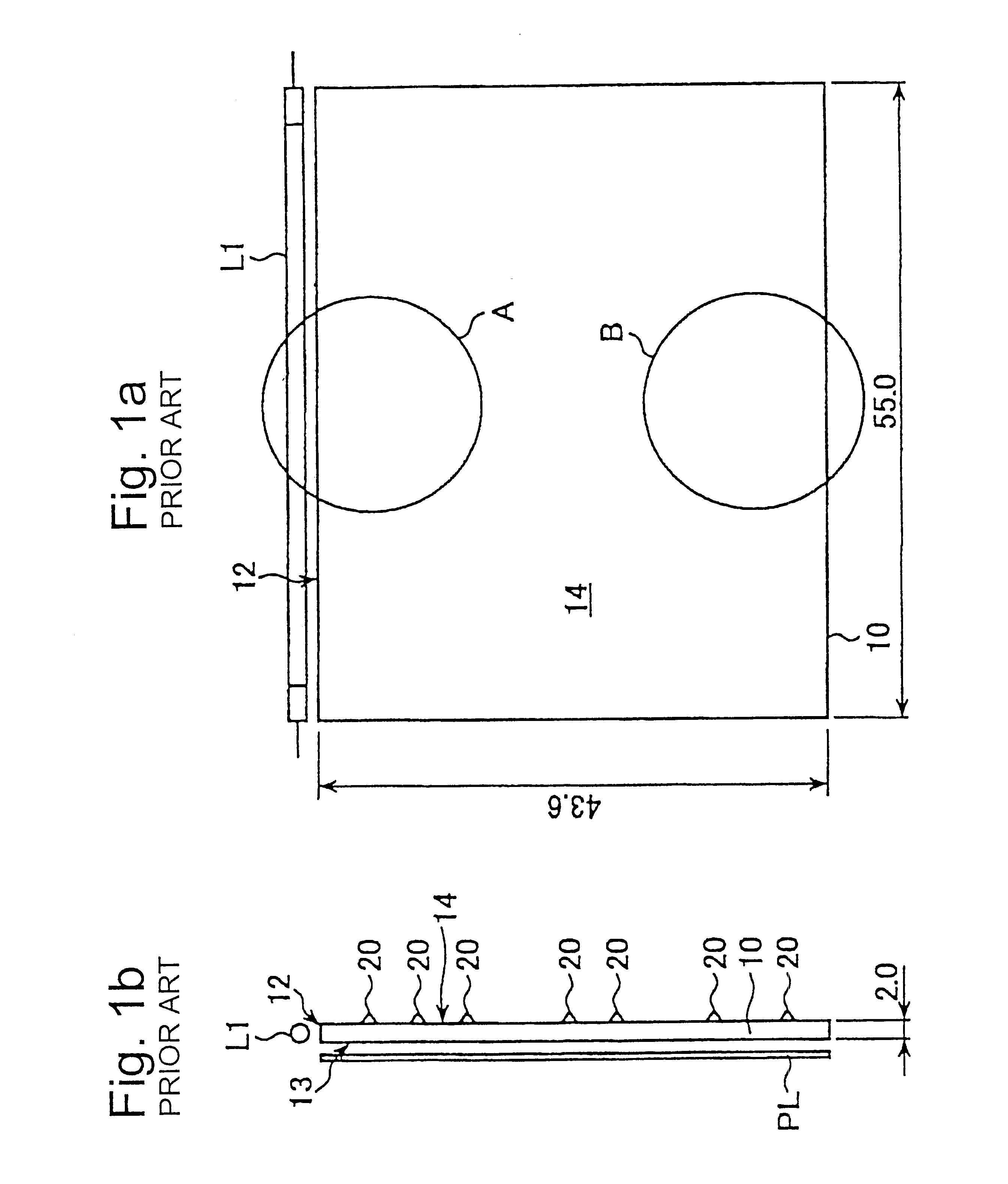
Cases where a great number of micro-reflectors are formed on a back face of a light guide plate as described above are subject to a problem that the micro-reflector arrangement is apt to be visible through the light guide plate.
However, size reduction is subject to a practical limit.
According to another technique, a light diffusion plate having a strong diffusibility is disposed on an emission face, which brings loss of light.
However, if this idea is applied, local pattern rather appears, which is probably caused by "fluctuation of arranging rate", failing to provide good results.

Method used


Image

  • Guide plate, surface light source device and liquid crystal display
  • Guide plate, surface light source device and liquid crystal display
  • Guide plate, surface light source device and liquid crystal display

Examples


Embodiment Construction

Embodiments in accordance with the present invention are described hereafter by referring to the attached drawings. It should be noted that factors such as size and shape of elements are exaggerated, as required, for the sake of explanation. Further, elements commonly employed in a plurality of drawings, are denoted by common references and repeated descriptions are omitted as required.

Referring to FIG. 3, a perspective view of a liquid crystal display LCD of an embodiment in accordance with the present invention is shown. The liquid crystal display LCD is applied to, for instance, portable phones, LCD television sets, mobile-computing devices or the like, being provided with a surface light source device SL backlighting a liquid crystal display panel LP.

The surface light source device SL comprises a light guide plate 3O, primary light source L2, reflection sheet RF and light diffusion sheet DF. The light guide plate 30 is a light-permeable member made of as acrylic resin (PMMA resi...


PUM

PropertyMeasurementUnit
sizeaaaaaaaaaa
transparentaaaaaaaaaa
inner reflectionaaaaaaaaaa

Abstract

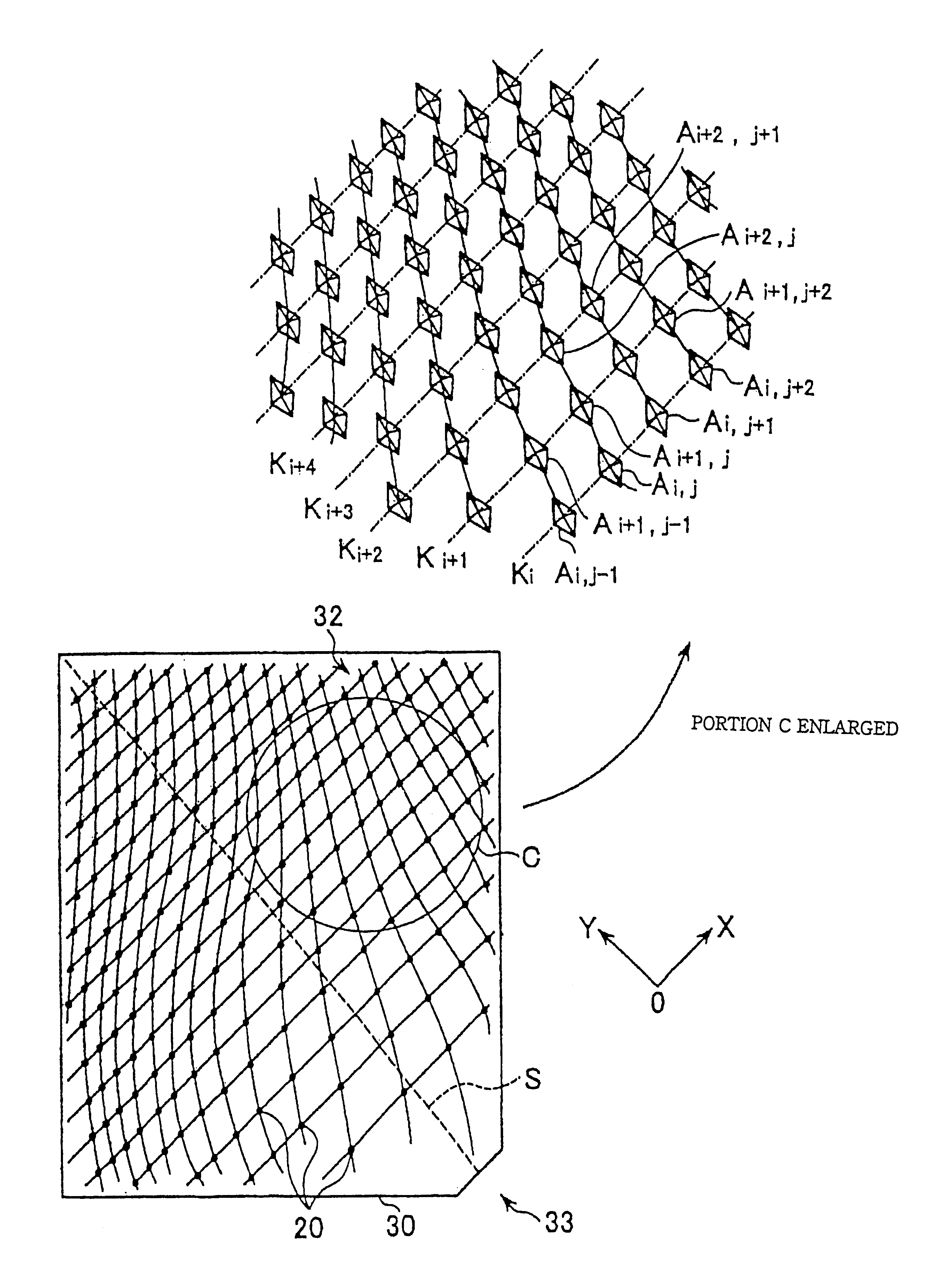
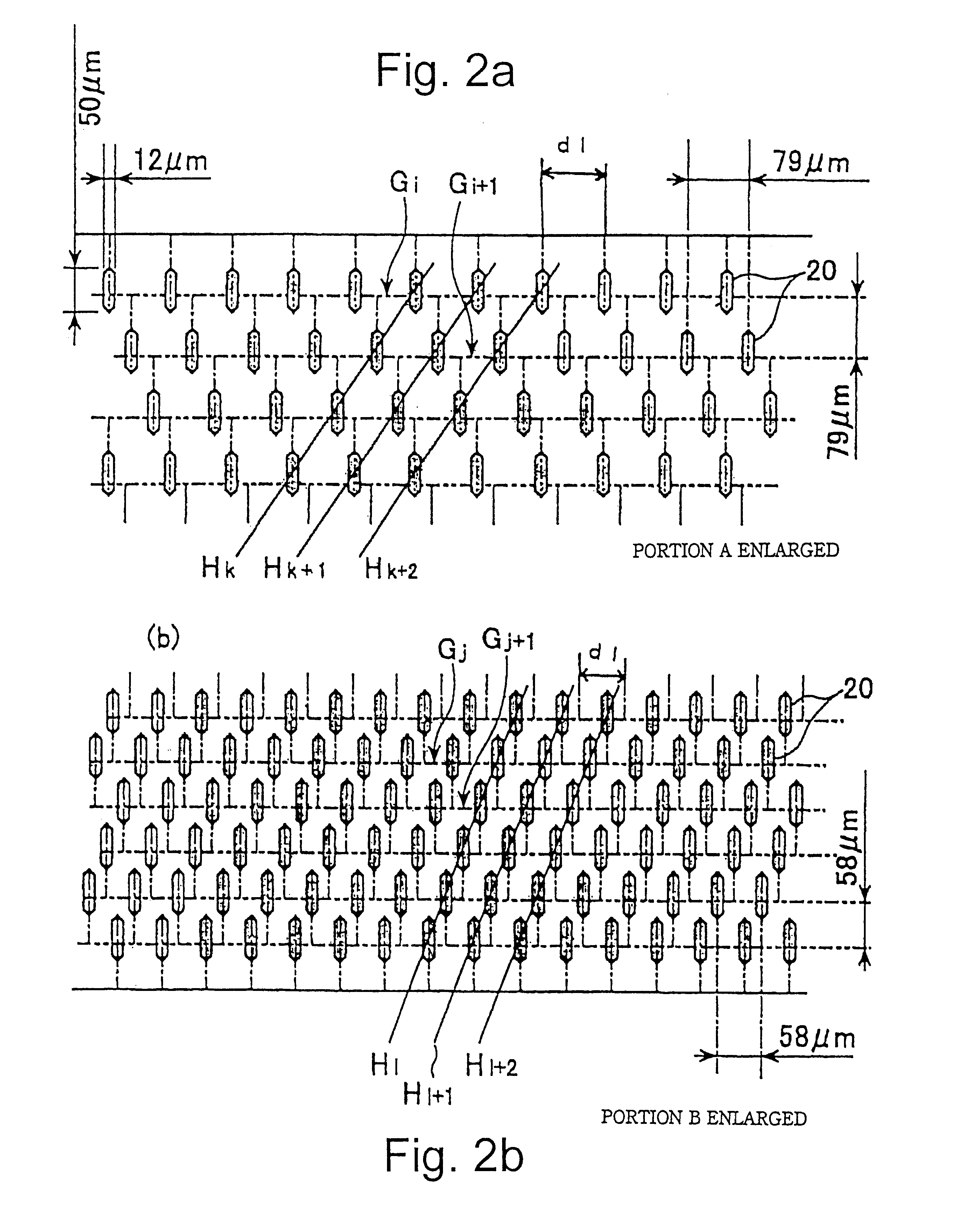
A surface light source device and LCD employing light guide plates having inconspicuous micro-reflector arrays are provided. Alight guide plate 30 illuminating an LCD panel of a surface light source device has a back face 32 provided with many micro-reflectors 20 arranged with sidewise intervals on imaginary lines Ki which are generally perpendicular to an imaginary reference line S with longitudinal intervals getting smaller according to an increasing distance from an incidence face 33. On each imaginary line Ki, the sidewise intervals get smaller or micro-reflector sizes get larger according to an increasing distance from the reference line S. Making many microreflector trios each of which consists of micro-reflectors arranged adjacent to each other and on any imaginary lines Ki to Ki+2, each of the trios has micro-reflectors are located generally on a straight line. Covering rate of the micro-reflectors increases according to an increasing distance from an incidence face 33. The imaginary lines Ki may be curved gently.

Description

1. Field of InventionThe present invention relates to a light guide plate, surface light source device and liquid crystal display, in particular to improvements of a light guide plate having a back face provided with a great number of micro-reflectors, a surface light source device employing an improved light guide plate and a liquid crystal display employing the surface light source device for illumination a liquid crystal display panel. The present invention is applied to liquid crystal displays for portable telephones, personal computers or car-navigation systems, being applied further to surface light source devices and light guide plates used therein.2. Related ArtAccording to a well-known prior art, a surface light source device has a light guide plate which is supplied with light sideways and outputs the light through an emission face after introducing the light into the light guide plate and applying direction-conversion, being broadly employed for illuminating an LCD panel ...

Claims


Application Information

Patent Timeline
Patent Type & Authority Patents(United States)
IPC IPC(8): F21V8/00G02B6/00F21Y101/02G02F1/1335G02F1/13357
CPCG02B6/0036G02F1/1335
Inventor OHKAWA, SHINGO
Owner ENPLAS CORP
Learn More