Control apparatus of induction motor

a technology of induction motor and control apparatus, which is applied in the direction of motor/generator/converter stopper, dynamo-electric gear control, dynamo-electric converter control, etc., can solve the problems of unstable phenomenon, shock in the vicinity of a switched frequency, and deterioration of control performan

Inactive Publication Date: 2003-08-26
HITACHI LTD
View PDF17 Cites 14 Cited by
  • Summary
  • Abstract
  • Description
  • Claims
  • Application Information

AI Technical Summary

Benefits of technology

In order to achieve the foregoing object, according to the present invention, there is provided a control apparatus of an induction motor, comprising: a detector for detecting a primary current of the induction motor; primary current component detecting means for detecting an exciting current and a torque current from the current detected by the detector; correcting means for outputting a correction voltage to set zero a difference between an exciting current command value and the exciting current outputted from the primary current detecting means; frequency voltage control means for outputting a frequency command and a voltage command based on an output of the correcting means, primary resistance, an inductance ratio between mutual inductance and secondary self-inductance, and leakage inductance of the induction motor; and at least one selected from fist to third constant correcting means, the first constant correcting means being for correcting the primary resistance based on a quantity obtained by multiplying a quantity of a voltage command outputted from the frequency voltage control means by the output of the correcting means, the quantity of the voltage command being a result of partial differentiation with the primary resistance, the second constant correcting means for correcting the leakage inductance based on a quantity obtained by multiplying a quantity of the voltage command outputted from the frequency voltage control means by the output of the correcting means, the quantity of the voltage command being a result of partial differentiation with the leakage inductance, and the third constant correcting means for correcting the inductance ratio based on a quantity obtained by multiplying a quantity of the voltage command outputted from the frequency voltage control means by the output of the correcting means, the quantity of the voltage command being a result of partial differentiation with the inductance ratio. Thus, among constants of the induction motor used for control, primary resistance, an inductance ratio or primary self-inductance, and leakage inductance can be set optimal according to a running state, making it possible to suppress the deterioration of control performance caused by the setting errors or the fluctuation of these constants during running.

Problems solved by technology

If there is a difference between the constant of the induction motor set in the control apparatus and an actual constant because of such constant fluctuation, then control performance may be deteriorated or an unstable phenomenon may occur.
Consequently, shocks may occur in the vicinity of a switched frequency during acceleration / deceleration.

Method used


Image

  • Control apparatus of induction motor
  • Control apparatus of induction motor
  • Control apparatus of induction motor

Examples


Embodiment Construction

Next, the preferred embodiments of the present invention will be described with reference to the accompanying drawings.

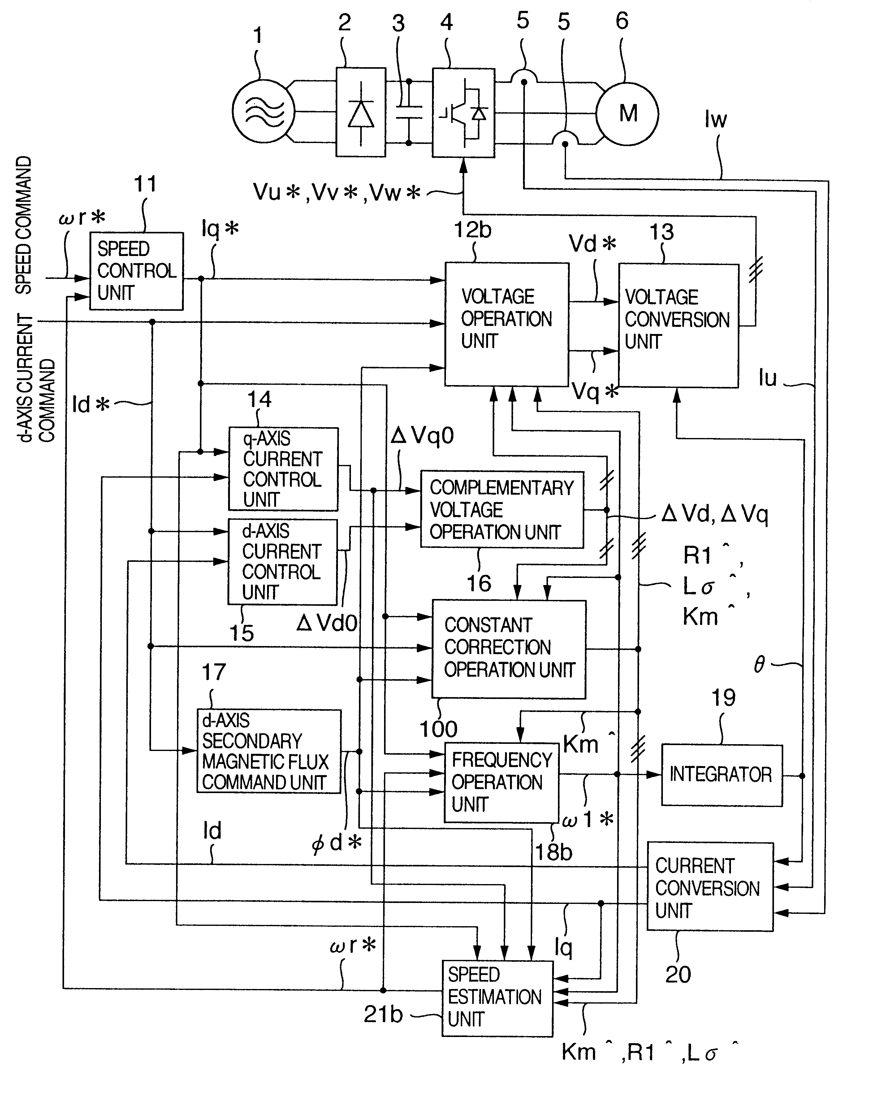
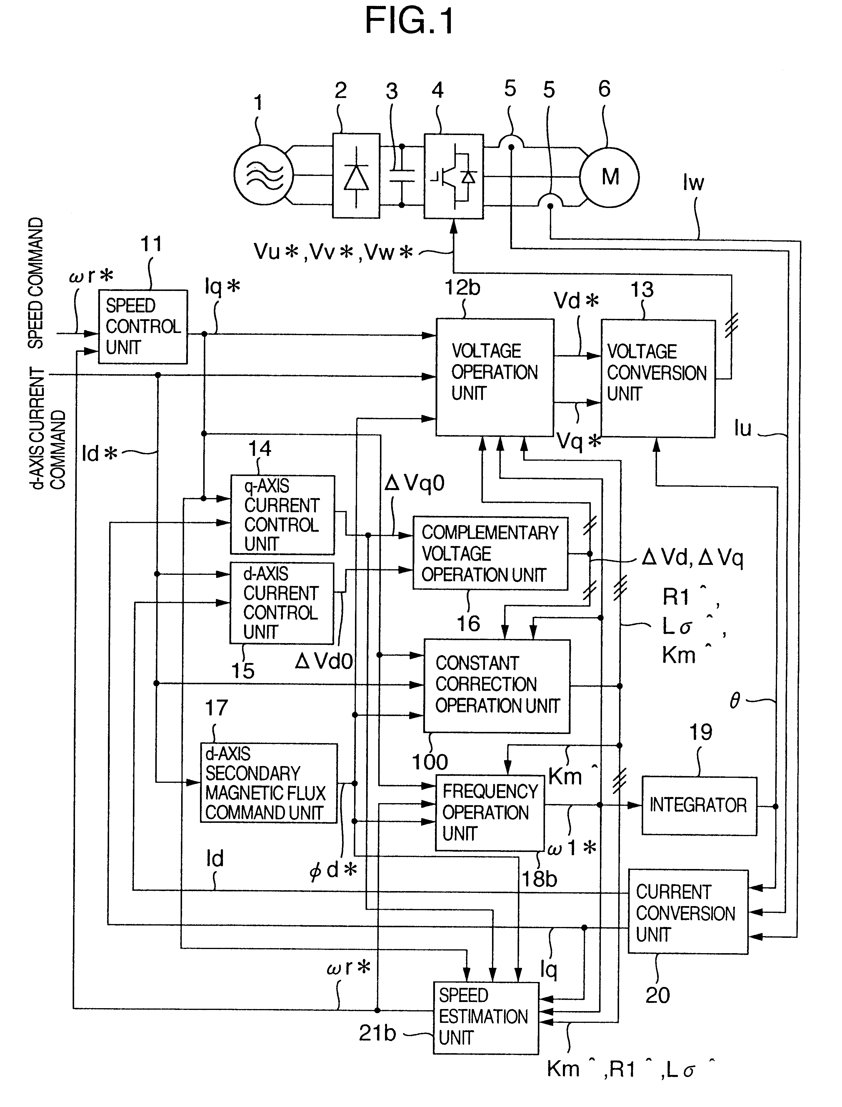
FIG. 1 illustrates the constitution of a control apparatus for an induction motor according to a first embodiment of the present invention. In FIG. 1, a reference numeral 1 denotes an AC power source; 2 a converter; 3 a smoothing capacitor; 4 an inverter; 5 a current detector; 6 an induction motor; 11 a speed control unit; 12b a voltage operation unit; 13 a voltage conversion unit; 14 a q-axis current control unit; 15 a d-axis current control unit; 16 a correction voltage operation unit; 17 a d-axis secondary magnetic flux command unit; 18b a frequency operation unit; 19 an integrator; 20 a current conversion unit; 21b a speed estimation unit; and 100 a constant correction operation unit. The same components as in the conventional example of FIG. 3 are denoted by the same reference numerals, and so the explanation of these components will be omitted.

The voltage oper...


PUM


Abstract

An induction motor control apparatus includes a first constant correction unit for correcting primary resistance based on quantity obtained by multiplying quantity of a voltage command from a frequency voltage control unit by the output of a correction unit, the quantity of the voltage command being a result of partial differentiation with the primary resistance; a second constant correction unit for correcting the inductance based on quantity obtained by multiplying quantity of the voltage command, the quantity of the voltage command being a result of partial differentiation with the inductance; and a third constant correction unit for correcting the inductance ratio based on quantity obtained by multiplying quantity of the voltage command, the quantity of the voltage command being a result of partial differentiation with the inductance ratio, suppressing the deterioration of control performance caused by the setting errors.

Description

1. Field of the InventionThe present invention relates to a control apparatus for an AC motor, and more particularly, it relates to a technology for estimating a constant of the AC motor.2. Description of the Related ArtHeretofore, as a control apparatus for an AC motor, to which a control method is applied, there has been available a control apparatus having such a constitution as shown in FIG. 3. In FIG. 3, a reference numeral 1 denotes an AC power source; 2 a converter; 3 a smoothing capacitor; 4 an inverter; 5 a current detector; 6 an induction motor; 11 a speed control unit; 12a a voltage operation unit; 13 a voltage conversion unit; 14 a q-axis current control unit; 15 a d-axis current control unit; 16 a correction voltage operation unit; 17 a d-axis secondary magnetic flux command unit; 18a a frequency operation unit; 19 an integrator; 20 a current conversion unit; and 21a a speed estimation unit.An AC voltage outputted from the AC power source 1 is rectified by the converter...

Claims


Application Information

Patent Timeline
Patent Type & Authority Patents(United States)
IPC IPC(8): H02P21/14H02P27/04H02P21/00H02P21/16H02P21/18H02P21/22H02P21/24H02P23/07H02P23/14H02P29/00
CPCH02P21/0042H02P21/145H02P21/146H02P2207/01H02P21/16H02P21/18H02P21/26
Inventor ISHIDA, SEIJI
Owner HITACHI LTD
Why Eureka
Try Eureka