Rigid insert for engine welder cowing

a technology for engine welders and inserts, applied in the direction of roofs, packaging goods, liquid handling, etc., can solve the problem of substantial thin cross-section of depressed, and achieve the effect of convenient insertion and thin cross-section

Inactive Publication Date: 2003-09-16
LINCOLN GLOBAL INC
View PDF5 Cites 31 Cited by
  • Summary
  • Abstract
  • Description
  • Claims
  • Application Information

AI Technical Summary

Benefits of technology

In accordance with the present invention, there is provided a rigid insert for mounting in the cut away portion at the top corner of a cowing in a standard engine driven welder. This insert is made from a rigid material, such as stamped sheet metal or high hardness plastic. It has an essentially inverted cup shape configuration opened from the top and side. This hard inverted cowing insert has a lower generally flat, rigid wall with an opening surrounding the upstanding tube be it a filler neck or filler neck in combination with the upper portion of a mechanical fuel gage. The apertured lower wall of the rigid cowing insert is provided with a soft plastic or elastomeric grommet which merely fills the small gap between the opening in the rigid lower wall and the upstanding element

Problems solved by technology

This depression could be provided by a metal drawing action; however, such drawing action would be too

Method used


Image

  • Rigid insert for engine welder cowing
  • Rigid insert for engine welder cowing
  • Rigid insert for engine welder cowing

Examples


Embodiment Construction

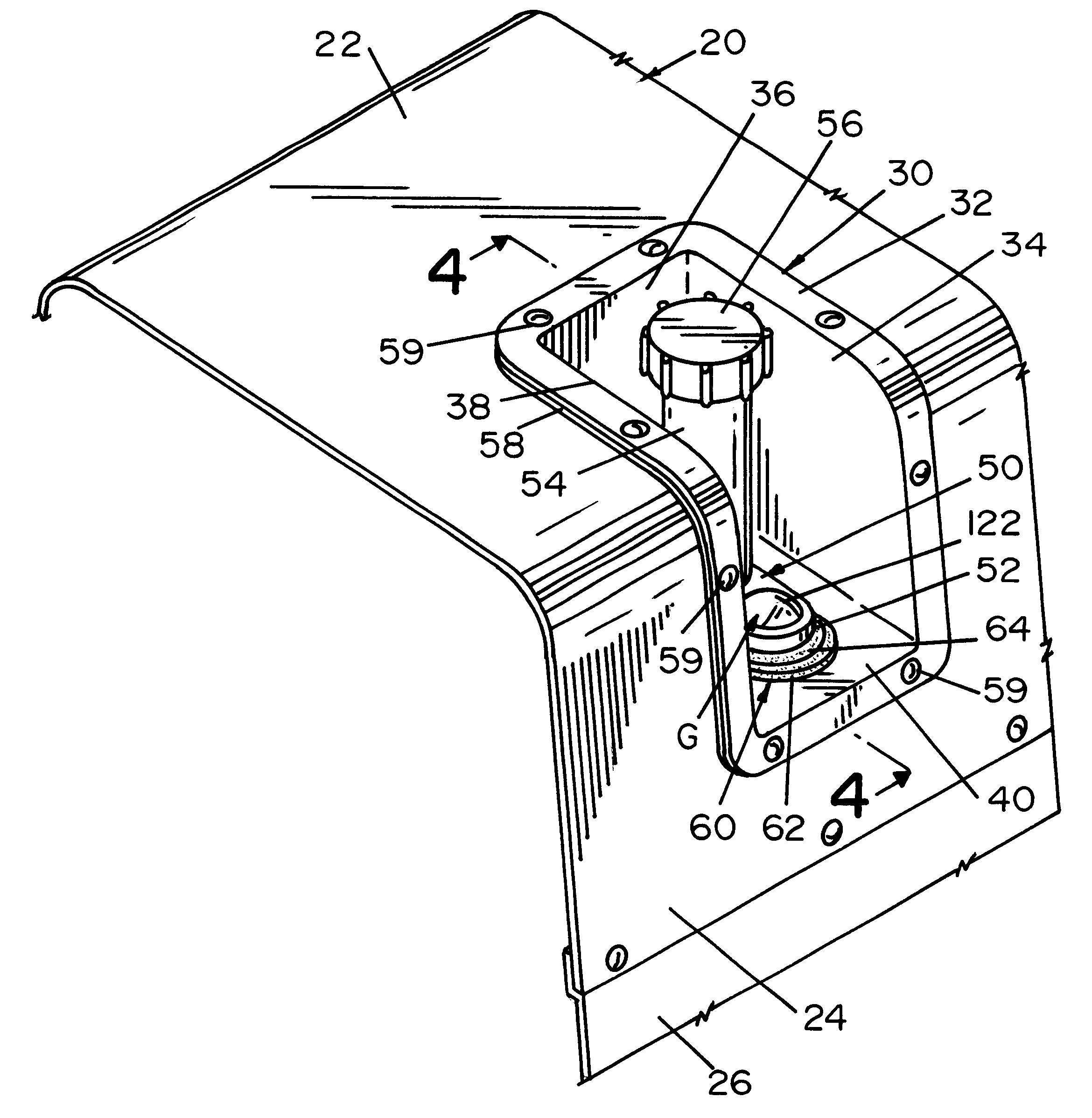
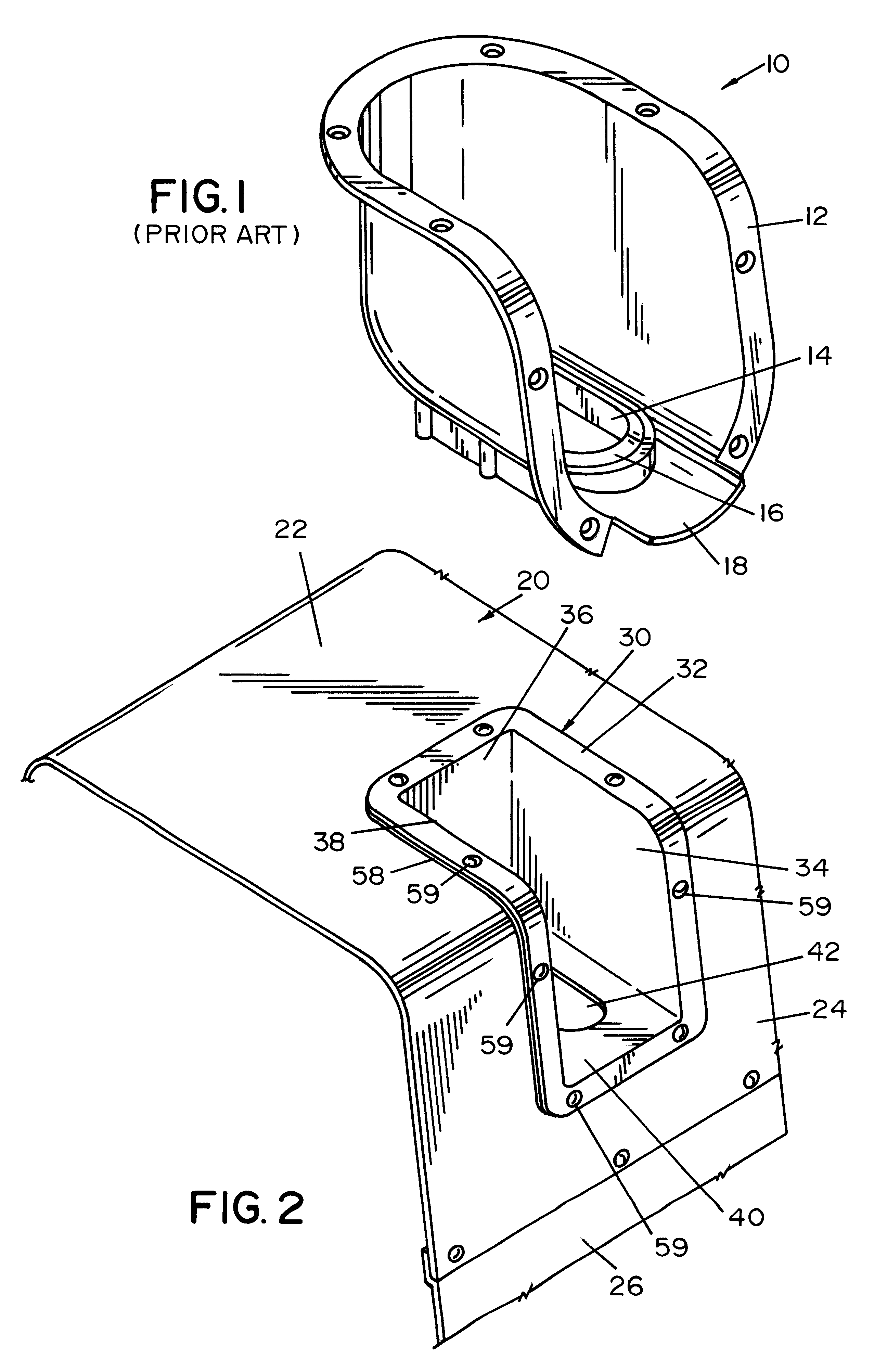
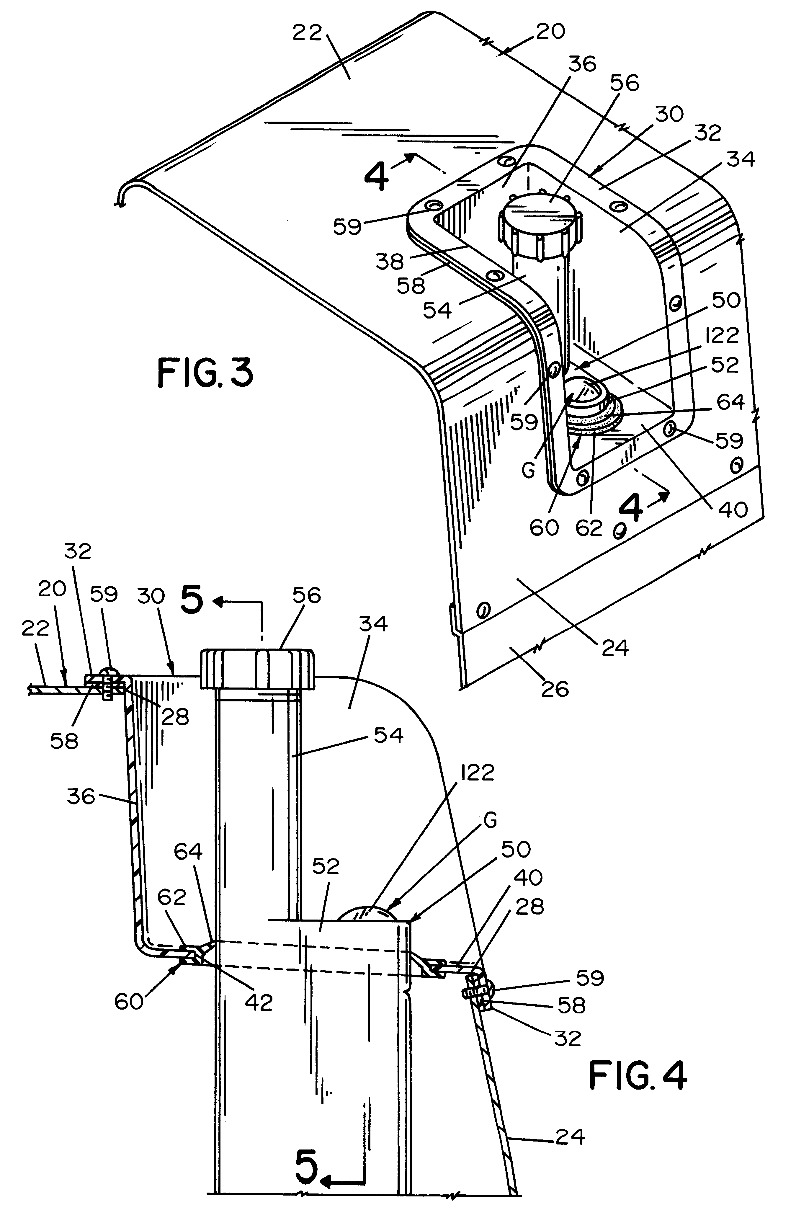
Referring now to the drawings wherein the showings are for the purpose of illustrating the preferred embodiment only and not for the purpose of limiting same, FIG. 1 shows a prior art escutcheon 10 with a one piece plastic body including an outwardly extending flange 12 and a lower opening 14 around which is a rigid sealing strip 16. Overflow lip 18 directs spilled fuel outwardly from the escutcheon over the side of the engine welder, as shown in Bender U.S. Pat. No. 6,263,926 and Trinkner U.S. Pat. No. 6,172,332. Escutcheon 10 is formed from a plastic material that closes a cut away corner portion 20 of the cowing over the top of the engine welder. Consequently, the plastic must be a compromise between the necessary support for the cowing and the upstanding filler tube as well as the flexibility needed for forming a fuel tight seal around the upstanding filler tube. In this compromise, the seal around the filler tube is not tight and it is difficult to push the filler tube through ...


PUM

PropertyMeasurementUnit
Lengthaaaaaaaaaa
Flexibilityaaaaaaaaaa
Hardnessaaaaaaaaaa

Abstract

A rigid inverted insert for mounting on the top panel of a rigid cowing of an engine welder, which cowing has a cut away opening in a top panel for allowing access to the top opening of a fuel filler tube extending from a low fuel tank to a position adjacent the rigid cowing. The novel insert has a lower wall generally to the top panel, but substantially below the top panel wherein the lower rigid wall has a central opening surrounding the filler tube to define a peripheral gap around the tube and a soft grommet or seal is mounted in the central opening and fixed to the insert.

Description

The present invention relates to an engine welder and more particularly to a novel rigid insert to support the cowing of a fuel tube of an engine welder.INCORPORATION BY REFERENCEThe present invention relates to an engine welder having a cut away portion in the upper housing to accommodate a standard filler tube extending from a lower fuel tank. When this fuel tank arrangement was first introduced in the Ranger 8 by The Lincoln Electric Company, the cut away was in the top panel of the cowing with a plastic escutcheon mounted around the filler tube to enclose the cut away and support the tube. When it was desired to incorporate a vertically extending mechanical gage with the filler tube, it was no longer practical to bring both the filler tube and gage to the top panel of the cowing. Thus, an escutcheon design was developed to accommodate both the upper neck of the filler tube and the top dial or indicator of the gage. This escutcheon was constructed of a single piece of plastic as ...

Claims


Application Information

Patent Timeline
IPC IPC(8): B23K9/32
CPCB23K9/32
Inventor VICKERS, ROBERT V.
Owner LINCOLN GLOBAL INC
Why Eureka
Try Eureka