Device for curtailing electric demand

a technology for curtailing electric demand and devices, applied in the direction of constant-current supply dc circuits, dc source parallel operation, ac network voltage adjustment, etc., can solve the problems of a large number of workers home, incurred significant economic losses, and lost production

Inactive Publication Date: 2003-09-16
HOWARD JOHN E
View PDF4 Cites 136 Cited by
  • Summary
  • Abstract
  • Description
  • Claims
  • Application Information

AI Technical Summary

Problems solved by technology

Customers who did shut down sent thousands of workers home, lost production and incurred significant economic losses.
Therefore, each such device would have to be custom-programmed for each EMS, and the associated cost would be restrictive, if not prohibitive.
However, this system and the vast majority of EMS designs in service today have no communication pathway that enables either RTP response or remote curtailment capability.
While the patent is entitled "Energy Management System", the claims do not cover the control of energy end-uses.
In concept, it can curtail demand and respond to RTP, but it accomplishes this by the slow and awkward procedure of reprogramming the EMS over a telephone line.
The method described is not practical for thousands of customers who may have to respond in a timeframe of minutes.
Conceivably the EMS could provide price response, but the claims don't cover this capability.
In other words, this patent describes an entire EMS, which would be expensive, although it would provide functionality and potential cost savings beyond the typical, autonomous EMS.
As in the previous case, implementing this system would require installation of an entire EMS at substantial cost.
If one assumes the embodiment of Scarpelli's application includes a full EMS, significant cost will be incurred to implement it and to establish the required communication pathways.
If large numbers of EMSs are involved, reprogramming becomes a daunting and costly task due to the many different protocols, programming languages, program structures, and physical programming interfaces that must be dealt with.
Further complicating this task is that each facility has its own mix of electrical loads and control requirements.
Thus, Hedman is limited to curtailing by a fixed percentage, unless the memory is reprogrammed at the site.
Furthermore, the device allows the customer to be curtailed within one minute of sending a command from a central location.

Method used


Image

  • Device for curtailing electric demand
  • Device for curtailing electric demand
  • Device for curtailing electric demand

Examples


Embodiment Construction

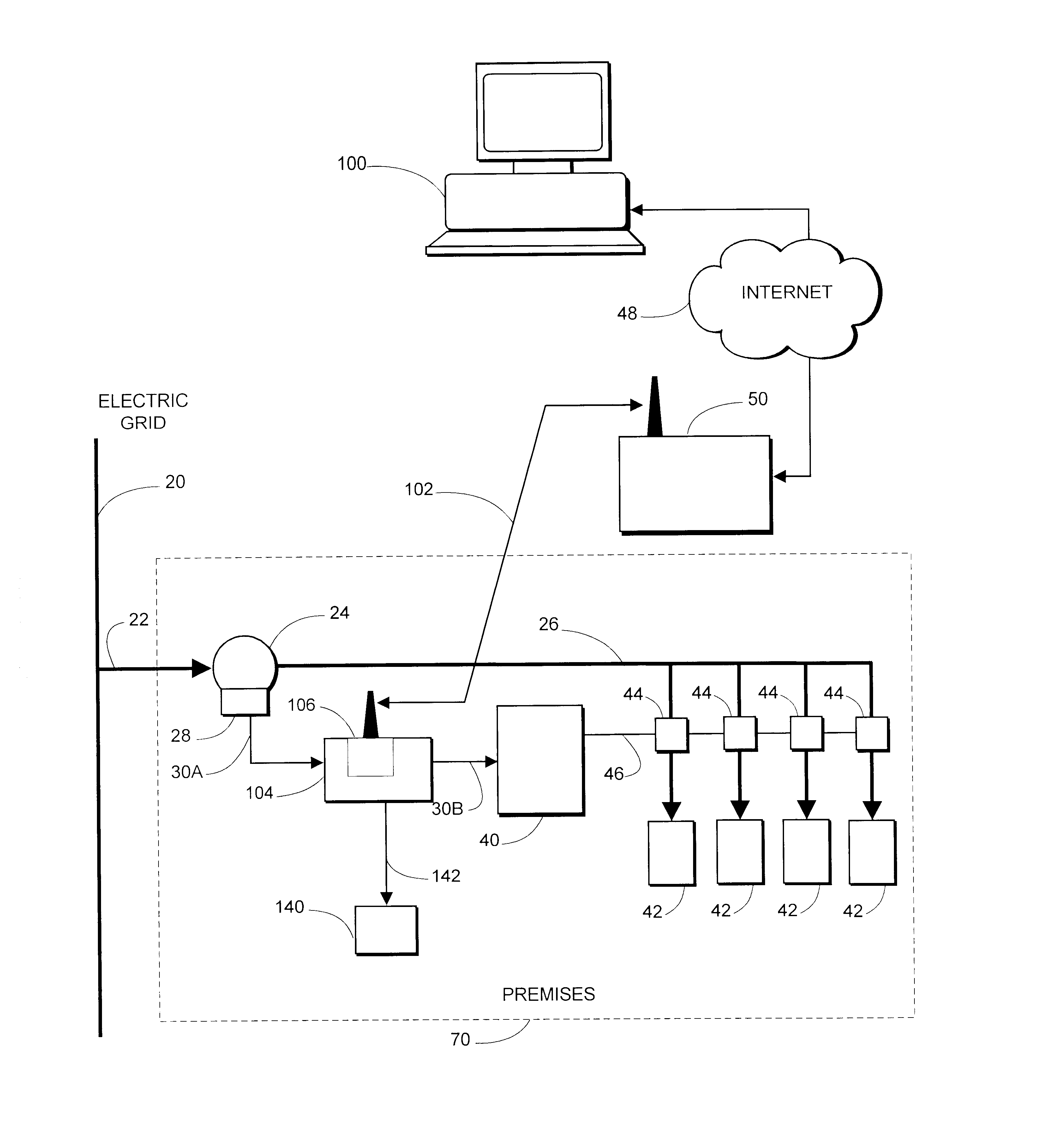
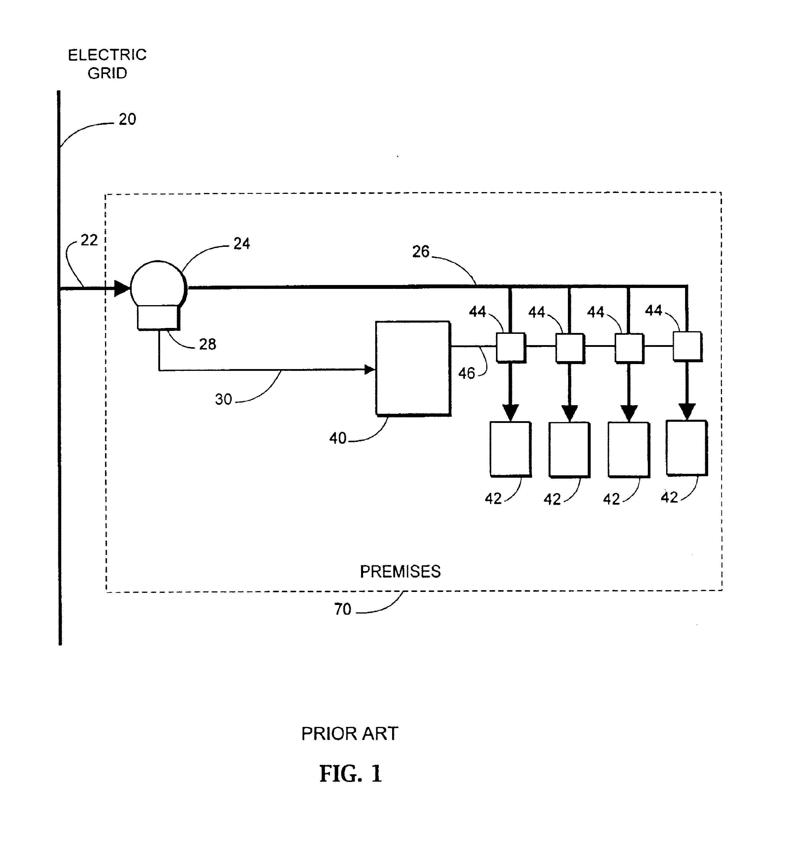
The description that follows is intended to be exemplary, and not limiting. FIG. 1 is a block diagram showing the application of a typical energy management system (EMS). This diagram represents certain implementations of prior art, particularly those that are suitable for installation of the device for curtailing electric demand of the present invention. An electric grid 20 supplies power to a premises 70 though an electric service 22. An electric meter 24 measures the quantity of electrical energy consumed in premises 70. A plurality of branch circuits 26 distributes electrical energy throughout premises 70 to a plurality of electric end-use devices 42. An energy management system (EMS) 40 communicates through a signal network 48 to a plurality of control components 44, each of which can activate, deactivate, or modulate the connected electric end-use device 42. Electric meter 24 incorporates a pulse output 28, which is connected to EMS 40 by a pulse signal connection 30.
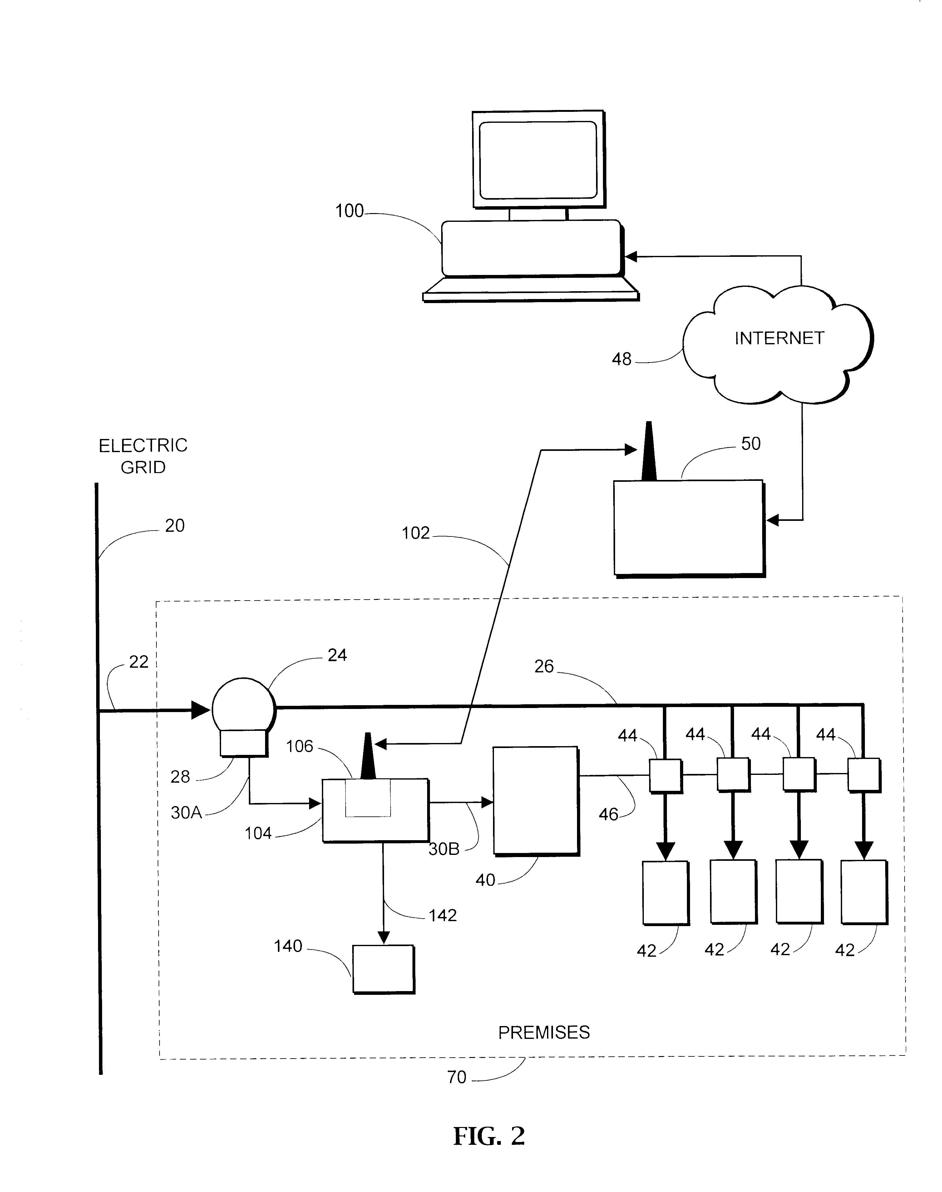
FIG. 2 is...


PUM


Abstract

A device for curtailing electric demand is suitable as a tool for responding to the real-time pricing of electrical energy or for reducing demand during power shortages. The device (104) according to the present invention works in conjunction with an energy management system (40), which receives demand signals from an electric meter (24). Upon executing a curtailment command sent to the device (104) through a communications network (48, 50, 102), device intercepts and biases the signal going to the energy management system (40), which, in effect, coerces it to reduce the demand upon the meter (24) and upon the electric grid (20).

Description

FEDERALLY SPONSORED RESEARCHNot ApplicableSEQUENCE LISTING OR PROGRAMNot ApplicableBACKGROUND--FIELD OF INVENTIONThe field of the invention relates generally to the utilization of electric power, and specifically to a device that can remotely curtail the electric demand of a premises during supply shortages and periods of high power prices.BACKGROUND--DESCRIPTION OF PRIOR ARTThe two primary components of electric bills are energy charges and demand charges. Energy is the amount of the commodity of electricity consumed, and it is measured in kilowatt-hours (kWh). Demand is the rate (that is, the pace) at which energy is consumed, and it is measured in kilowatts (kW). Demand charges are computed from the largest average demand of a sequence of equal time intervals, usually 15 minutes long. Both energy charges and demand charges can vary by time of use.Deregulation of the electric utility industry has been accompanied by the emergence of spot markets for electric power and access to th...

Claims


Application Information

Patent Timeline
Patent Type & Authority Patents(United States)
IPC IPC(8): H02J13/00H02J3/12H02J3/14
CPCH02J3/14H02J13/0086H02J13/00028H02J2310/60H02J2310/64H02J3/144Y04S50/10
Inventor HOWARD, JOHN E.
Owner HOWARD JOHN E
Why Eureka
Try Eureka