Snubbing unit with improved slip assembly

a technology of unit and assembly, which is applied in the direction of brake system, borehole/well accessories, manufacturing tools, etc., can solve the problems of die carrier not applying uniform force to the tubular, die carrier having a tendency to "rock", and affecting the effective and non-damaging gripping of the tubular

Inactive Publication Date: 2003-11-04
MCCOY CORPORATION
View PDF17 Cites 31 Cited by
  • Summary
  • Abstract
  • Description
  • Claims
  • Application Information

AI Technical Summary

Problems solved by technology

While these variations are not great in magnitude, they do often create a problem in relation to the prior art slip assembly.
This results in the die carriers not uniformly contacting the slip bowl, thus resulting in die carriers not applying uniform force to the tubulars or the die carriers having a tendency to "rock" in the slip bowl.
Both of these problems are detrimental to the effective and non-damaging gripping of tubulars.
Another disadvantage of prior art slip bowls is the comparatively high coefficient of friction (COF) between the die carrier's and the bowl's slip surfaces.
This is not easily carried out with the prior art slip assemblies such as seen in the Crowe reference because the die carriers are not firmly fixed in the slip bowl against lateral movement as torque is applied.

Method used


Image

  • Snubbing unit with improved slip assembly
  • Snubbing unit with improved slip assembly
  • Snubbing unit with improved slip assembly

Examples


Embodiment Construction

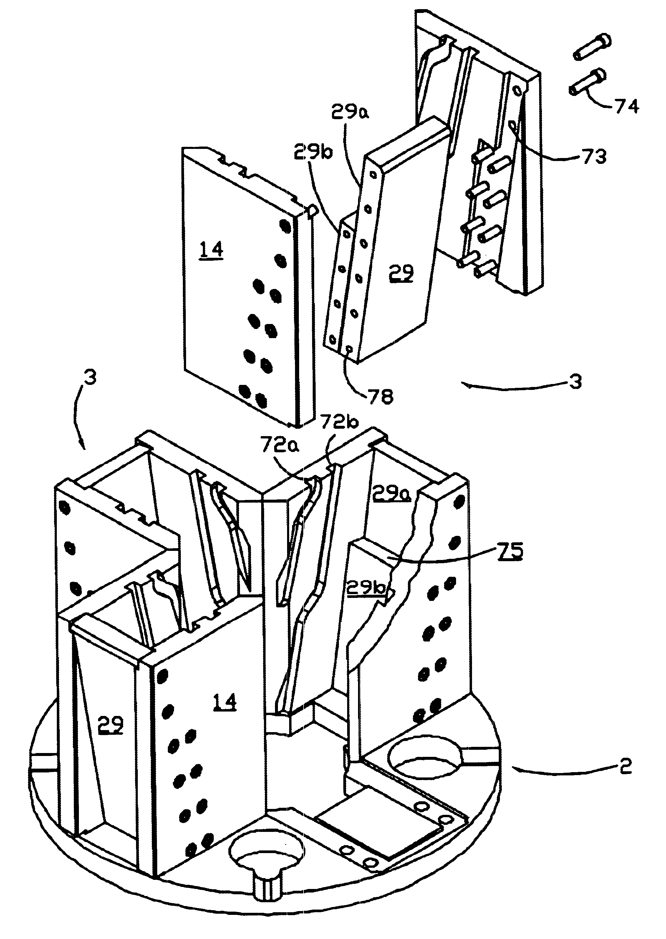
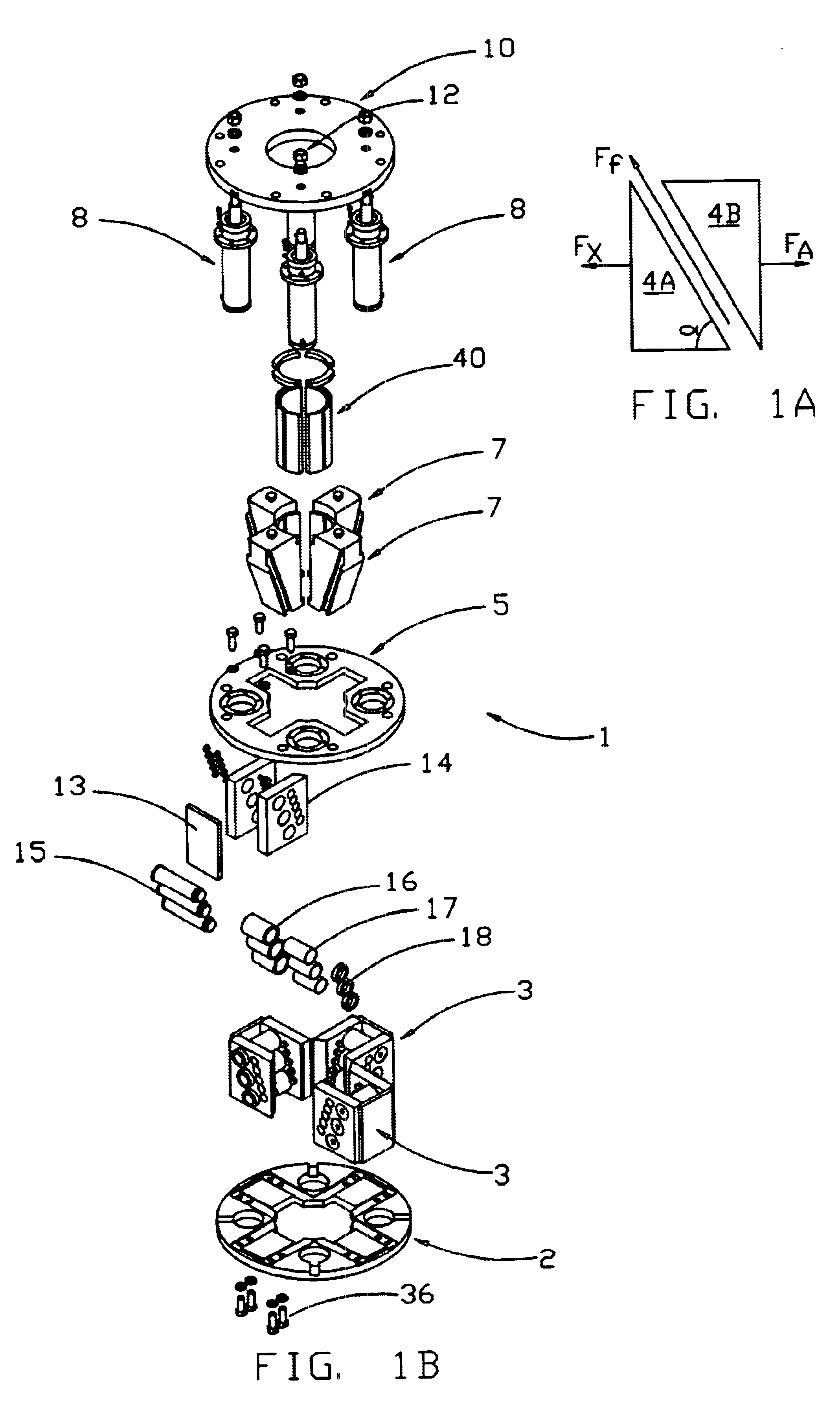
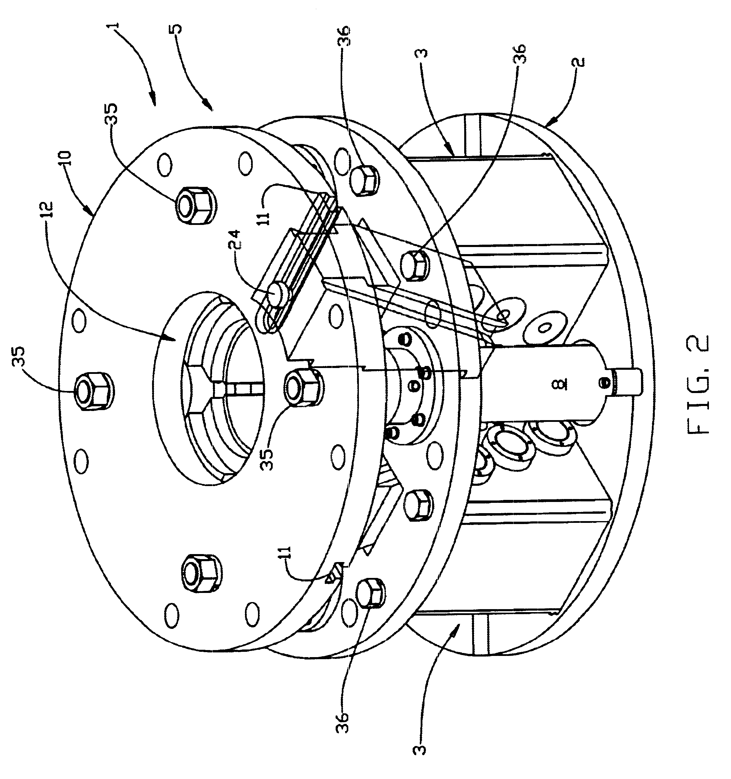
FIG. 1 is an exploded view illustrating the main components of the improved slip assembly 1. These main components include a base plate 2, slip frames 3, cylinder plate 5, die carriers 7, lifting cylinders 8, and slip ring 10. It can be seen that slip ring 10 includes a center aperture 12 and cylinder plate 5 and base plate 2 have corresponding center openings formed therein for allowing a tubular member to travel through the center of slip assembly 1. FIG. 2 illustrates how slip frames 3 and lifting cylinders 8 will be positioned between cylinder plate 5 and base plate 2 and secured into place by bolts 36. FIG. 3 more clearly shows slip frames 73 since with lifting cylinders 8, cylinder plate 5 and slip ring 10 have been removed. Each slip frame 73 will comprise two side frame sections 14 and one rear frame section 13 resting on base in plate 2. As best seen in FIG. 7, base plate 2 will include a depression or footing 59 and bolt apertures 60 to allow frame sections 13 and 14 to be...


PUM


Abstract

An improved snubbing unit including a snubbing unit base, a lifting assembly having a platform positioned above the base, a rotary table positioned on the snubbing unit, and a first slip assembly positioned on the rotary table. The first slip assembly further includes a base plate with a center aperture formed therein, at least two separate slip frames positioned on the base plate around the center aperture, wherein each of the slip frames includes a slip surface, and a die carrier positioned within each of the slip frames, wherein each of the die carriers also includes a surface for engagement with the slip surfaces of said slip frames. Additionally, a second slip assembly will be positioned on the snubbing unit.

Description

I. BACKGROUND OF THE INVENTIONThe present invention relates to slip assemblies used in the oil and gas drilling industry. In particular, the present invention relates to an improved slip surface which allows the die carriers of the slip assembly to apply greater radial force to the tubular member being gripped.Various types of slip assemblies are known in the art. U.S. Pat. No. 4,681,193 to Crowe discloses a typical slip assembly which is operated with hydraulic cylinders. The Crowe slip assembly has a slip bowl with an open top and bottom and which has an inwardly sloping slip surface of a continuous curvature around the inside parameter of the bowl. In essence, the slip bowl forms a funnel shaped slip surface. A plurality of slip die carriers (e.g., three) are designed to fit within the slip bowl. Each of the die carriers will include a sloping arcuate surface which has a curvature corresponding to the curvature of the bowl's slip surface. However, it will be understood that this ...

Claims


Application Information

Patent Timeline
Patent Type & Authority Patents(United States)
IPC IPC(8): B65H59/10B60TE21B19/10
CPCE21B19/10
Inventor BUCK, DAVID A.
Owner MCCOY CORPORATION
Why Eureka
Try Eureka