Hydraulic actuator and accumulator arrangement

a technology of accumulator and actuator, which is applied in the direction of mechanical equipment, power amplification, transportation and packaging, etc., can solve the problems of affecting the timely and/or correct positioning of the bogie of the landing gear, the potential failure and the inability to determine the condition of the separator piston. , to achieve the effect of reducing the flow area

Active Publication Date: 2018-08-09
AIRBUS OPERATIONS LTD
View PDF7 Cites 10 Cited by
  • Summary
  • Abstract
  • Description
  • Claims
  • Application Information

AI Technical Summary

Benefits of technology

[0010]It may be that the snubbing device is provided at least in part by means of geometrical features of the accumulator. It may be that the snubbing device is provided at least in part by means of a mechanical device, such as a spring mechanism for example, or a damper. It may be that the snubbing device comprises a metered cup system. Such a metered cup system may comprise a cup-to-cup arrangement that constrains the flow of a trapped volume of fluid progressively by restricting flow as the separator piston approaches and/or goes beyond its normal (fault-free) end of stroke position. The snubbing device may comprise multiple parts that are not directly joined together. The snubbing device may comprise two or more snubbing elements that are moveable relative to each other, for example causing a progressive constriction of flow of fluid. The snubbing elements may be moveable from a spaced apart position to a position in which the snubbi

Problems solved by technology

Such a separator piston has the potential for hidden failure.
That in turn may disrupt timely and/or correct positioning of the bogie of the landing gear.
When the interior of the accumulator is not readily visible there may be no convenient means for ascertaining the condition of the separator piston, other than via manual inspection during a time-consuming servicing operation.
Thus, such minor faults may remain undetected.
Such faults tend

Method used


Image

  • Hydraulic actuator and accumulator arrangement
  • Hydraulic actuator and accumulator arrangement
  • Hydraulic actuator and accumulator arrangement

Examples


Embodiment Construction

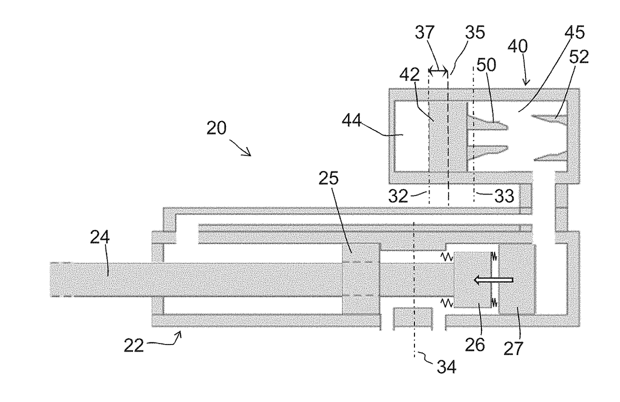
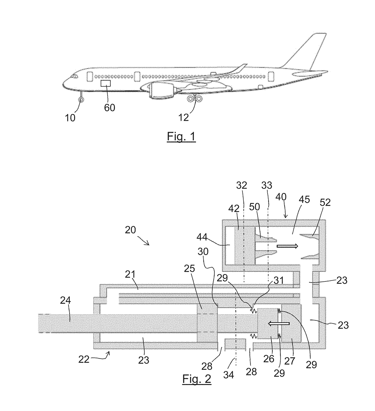
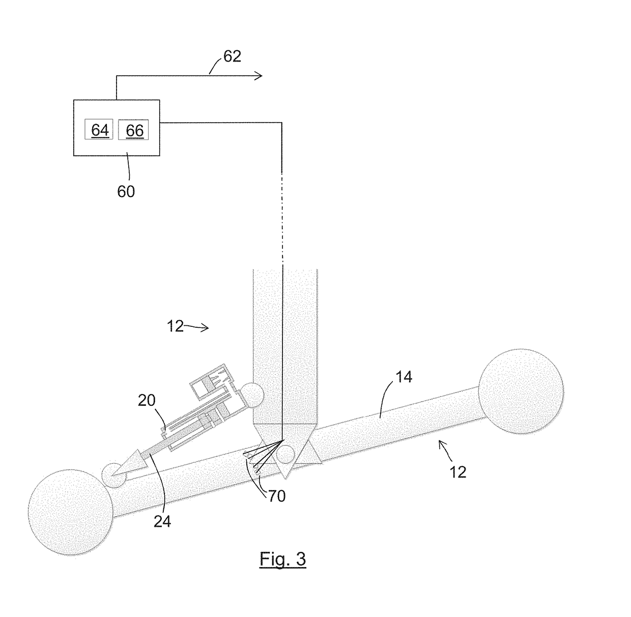
[0028]The embodiments generally relate to an aircraft landing gear system which includes a monitoring system which is arranged to detect a possible fault in the accumulator of a hydraulic system used to move a part of the landing gear. FIG. 1 shows an aircraft including a nose landing gear assembly 10 (the “NLG” assembly) and a main landing gear assembly 12 (the “MLG” assembly). The MLG assembly 12 includes wheels mounted on a bogie. Both NLG and MLG are retractable into respective landing gear bays on the aircraft. The embodiments concern detecting a failure mode in the accumulator associated with a hydraulically operated pitch trimmer for the bogie on the MLG 12. In the embodiment of FIG. 1, the detection of the failure mode is performed by a monitoring system 60 on the aircraft. The type of failure mode that is detected will now be explained briefly. In bogie pitch trimmer actuators of the prior art, there is the possibility of a progressive dormant failure mode in the accumulato...


PUM


Abstract

A landing gear system for an aircraft includes a retractable landing gear assembly, a hydraulic actuator for actuating movement part, for example a bogie of the landing gear assembly, and an accumulator associated with the actuator. The accumulator comprises a volume of pressurised gas separated from hydraulic fluid by a separator piston. Travel of the separator piston beyond a certain position is indicative of a fault. The accumulator includes a snubbing device that acts to slow movement of the separator piston beyond that position. A monitoring system measures the time taken for the movement of the landing gear part effected by the hydraulic actuator. If the measured time is longer than a threshold time, that is indicative of a possible fault in the accumulator, that might, without the snubbing, remain undetected and/or hidden from view.

Description

BACKGROUND OF THE INVENTION[0001]The present invention concerns a hydraulic actuator and accumulator arrangement, particularly but not exclusively, when provided on an aircraft landing gear assembly. The invention also concerns a method of detecting a fault in an accumulator.[0002]Embodiments of the present invention concern retraction of a landing gear assembly of an aircraft, wherein the assembly comprises a bogie. The retraction includes using an accumulator-energised hydraulic actuator to position the bogie into a bias position that is determined by the geometry of the gear / actuator and accumulator design. The accumulator comprises a volume of pressurised gas that is separated from hydraulic fluid by a separator piston. Such a separator piston has the potential for hidden failure. For example, if there is leakage of fluid / gas from one side of the separator piston to the other, the separator piston may during use travel beyond its normal range of positions in the accumulator. In ...

Claims


Application Information

Patent Timeline
IPC IPC(8): B64D45/00B64C25/22B64C25/34
CPCB64D45/0005B64C25/22B64C25/34B64C13/48B64C25/58B64D45/00F15B1/24F15B19/005B64D2045/0085F15B2201/205F15B2201/31B64F5/60F15B15/1409F15B2211/6336F15B2211/212F15B2201/505F15B1/021F15B15/14F15B2211/7051F15B19/00F15B2211/857F15B1/08
Inventor PAPADOPOULOS, CHRISTOPHERMARPLES, MATTHEWMOUNTY, ANDYFANOURAKIS, COSTASKING, GRAHAM
Owner AIRBUS OPERATIONS LTD
Why Eureka
Try Eureka