Strap fastener

a technology of fasteners and straps, which is applied in the direction of transportation items, hoisting equipment, wire tools, etc., can solve the problems of user suffering from great pain in the fingers, two problems can affect the use, etc., and achieve the effect of convenient and comfortable operation

Inactive Publication Date: 2003-11-04
HUANG HAN CHING
View PDF4 Cites 46 Cited by
  • Summary
  • Abstract
  • Description
  • Claims
  • Application Information

AI Technical Summary

Benefits of technology

It is an objective of the present invention to provide a strap fastener that a user can easily and comfortably operate.

Problems solved by technology

In use of this conventional strap fastener, a user can be bothered by two problems.
Firstly, the user may suffer from great pain in his fingers due to pressure because he has to press the first lever 40 with his fingers.

Method used


Image

  • Strap fastener
  • Strap fastener
  • Strap fastener

Examples


Embodiment Construction

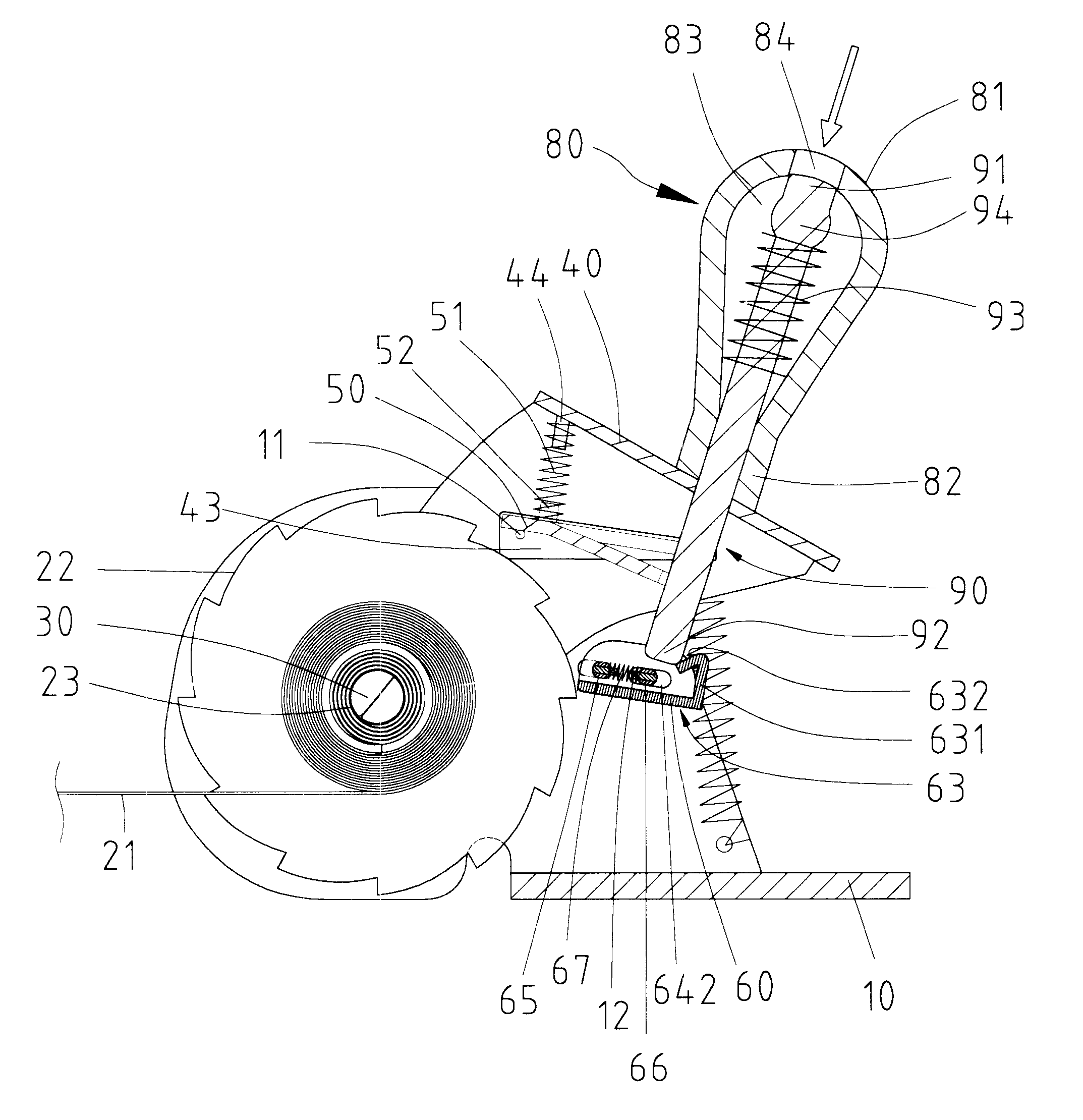
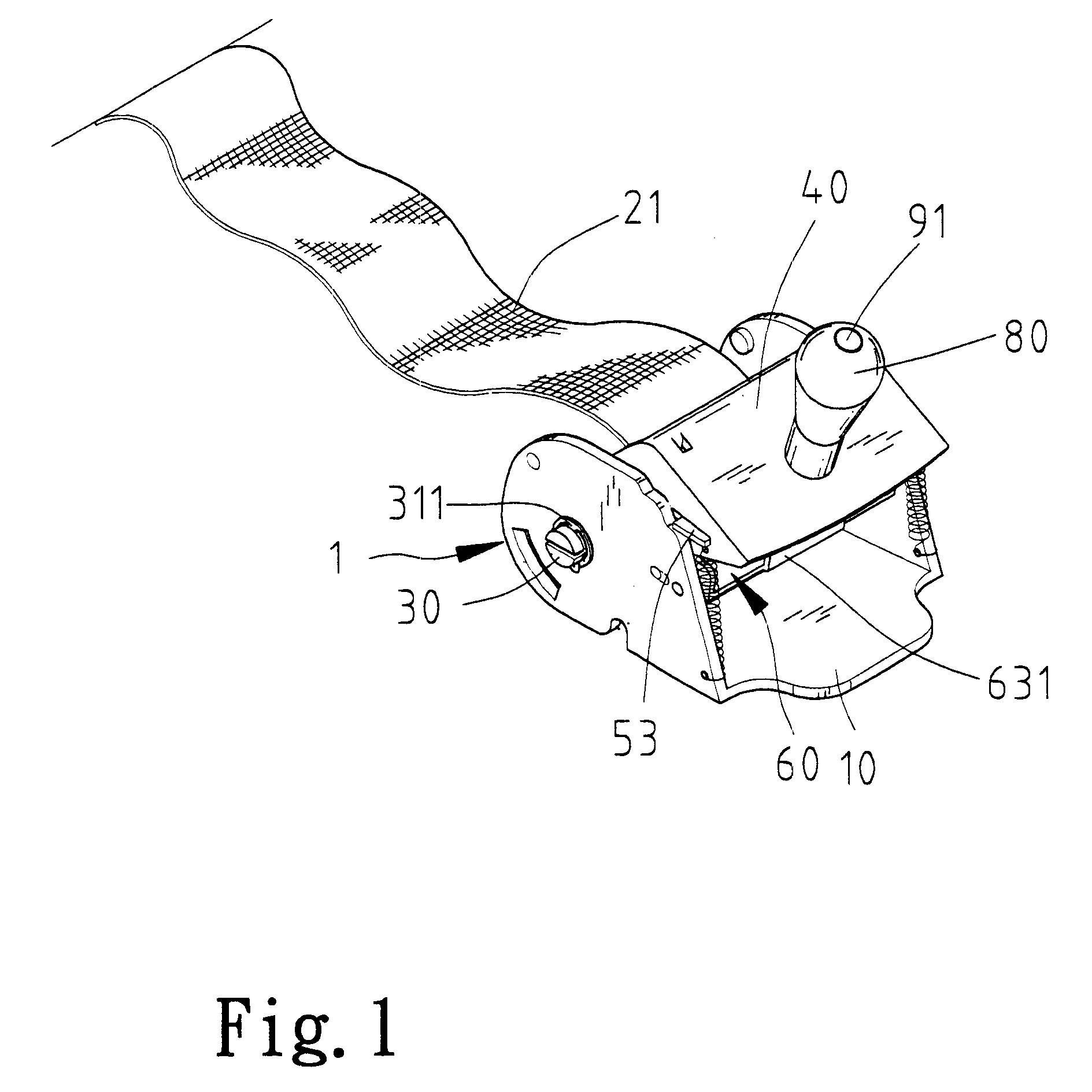
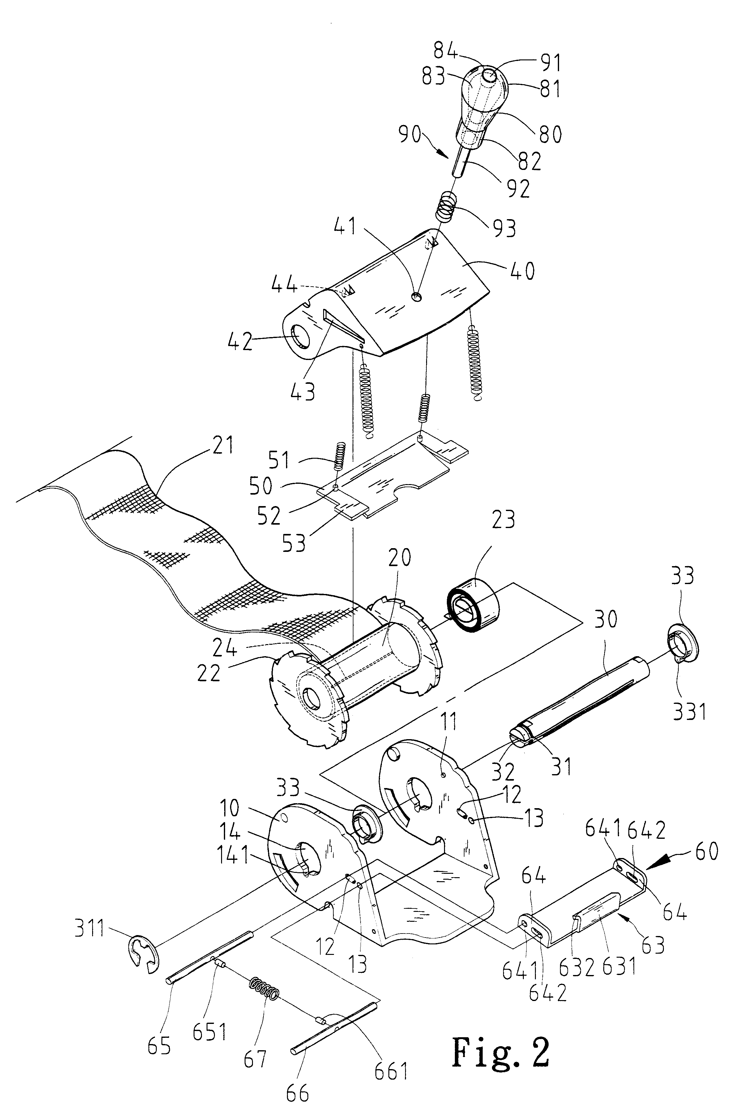
Referring to FIGS. 1 and 2, according to the preferred embodiment of the present invention, a strap fastener includes a base 10, a shaft 30 mounted on the base 10, a reel 20 rotationally mounted on the shaft 30, two ratchet wheels 22 formed on the reel 20, a lever 40 pivotally mounted on the base 10, a first detent 50 movably mounted on the lever 40 for engagement with the ratchet wheels 22, a second detent 60 movably mounted on the base 10 for engagement with the ratchet wheels 22.

The base 10 includes two side plates (not numbered) and an intermediate plate (not numbered) formed between the side plates. Each of the side plates is formed with a boss 11 on a side. The bosses 11 face each other. A slot 12, a first hole 13 and a second hole 14 are defined in each of the side plates. A recess 141 is defined in each of the side plates so that the recess 141 is communicated with the second hole 14.

The shaft 30 includes a first end, a second end, an annular groove 31 defined therein near t...


PUM

PropertyMeasurementUnit
pressureaaaaaaaaaa

Abstract

A strap fastener includes a base, a shaft mounted on the base, a reel rotationally mounted on the shaft, two ratchet wheels formed on the reel, a torque spring arranged between the reel and the shaft, a lever pivotally mounted on the base, a first detent movably mounted on the lever for engagement with the ratchet wheels, a second detent movably mounted on the base for engagement with the ratchet wheels, a wedge formed on the second spring-biased detent, a handle including a first end in which a hole is defined, a second end secured to the lever and a control element extending through the handle and the lever and including a first end exposed through the hole defined in the first end of the handle and a second end in engagement with the wedge. The first end of the control element can be pressed so as to move the second end of the control element from a position for engaging the second detent with the ratchet wheels to a second position for disengaging the second detent from the ratchet wheels.

Description

BACKGROUND OF INVENTION1. Field of InventionThe present invention is related to a strap fastener and, more particularly, to a strap fastener for use in boats.2. Related Prior ArtIn Taiwanese Patent Publication No. 361404 issued to the applicant of the present application, a strap fastener for use in boats is disclosed. This conventional strap fastener includes a base 10 and a reel 20 rotationally mounted on the base 10. A strap 21 is secured to and can be wound on the reel 20. Two ratchet wheels 22 are formed on the reel 20 so that the strap 21 is located between the ratchet wheels 22. A first lever 40 is pivotally mounted on the base 10. Movably mounted on the first lever 40 is a first detent 50 for engagement with the ratchet wheels 22. Two springs 521 are compressed between the first detent 50 and a stop 43 extending from the first lever 40 for biasing the first detent 50 into engagement with the ratchet wheels 22. Thus, pivotal motion of the first lever 40 in a first direction r...

Claims


Application Information

Patent Timeline
Patent Type & Authority Patents(United States)
IPC IPC(8): B60P7/08B60P7/06B66D3/00B66D3/14
CPCB60P7/083B66D3/14Y10T24/21Y10T24/2175
Inventor HUANG, HAN-CHING
Owner HUANG HAN CHING
Why Eureka
Try Eureka