Zero stop adjustable rifle scope

a scope and zero-stop technology, applied in the field of telescope scopes, can solve the problems of reducing the number of clicks available to adjust the position of the scope, serious limiting the usefulness of the rifle for shooting at long-range targets, and difficult or impossible accurate adjustments

Inactive Publication Date: 2003-11-11
LIGHTFORCE USA
View PDF20 Cites 73 Cited by
  • Summary
  • Abstract
  • Description
  • Claims
  • Application Information

AI Technical Summary

Benefits of technology

It is another object of the present invention to provide such a riflescope that enables the user to set the "zero-in" point on the riflescope at any point of the riflescope range and still use the full range of adjustment of the adjustment knob.
It is a further object of the present invention to provide such a riflescope that uses "1 / 4 minute per click" fine adjustment setting for greater accuracy.
These and other objects are met by a zero stop riflescope adjustment mechanism that allows a user to establish the "zero point" at any point in the range of the scope, and still maintain 1 / 4 minute clicks and unlimited rotations of the adjustment knob. The mechanism includes an adjustment bolt longitudinally aligned inside a cylindrical-shaped adjustment body that fits into a standard threaded hole formed on the turret of the riflescope. The adjustment bolt is a T-shaped structure with upper and lower threaded sections and a wide, central circular collar. During assembly, the lower threaded section of the adjustment bolt is connected to a lower threaded bore formed inside the adjustment body. The lower neck of the adjustment body connects to the threaded bore while the lower end extends into the hole formed on the turret and contacts the rector tube. When the adjustment bolt is rotated inside the adjustment body threaded bore, the distal end of the adjustment bolt advances or withdraws from the hole in the turret to change the angular position of the rector tube inside the riflescope.
Threadingly attached to the threaded upper section of the adjustment bolt that extends above the index dial is a stop ring. Attached to the outer perimeter of the stop ring is a downward extending tongue member that contacts the upward extending tab element formed on the index dial when the stop ring is rotated downward and positioned against the index dial. Together, the tab element and tongue member act as a stop means to prevent downward advancement of the stop ring over the adjustment bolt.

Problems solved by technology

If the clicks are difficult to hear or feel or if the environment is dark, accurate adjustments can be difficult or impossible to make.
Thus, the total number of clicks available for adjusting the position of the scope is reduced which seriously limits the usefulness of the rifle for shooting at long-range targets.
Another drawback with using a relatively large calibration such as a "1 click equals 1 inch standard" is that it introduces a greater error at greater ranges.

Method used


Image

  • Zero stop adjustable rifle scope
  • Zero stop adjustable rifle scope
  • Zero stop adjustable rifle scope

Examples


Embodiment Construction

)

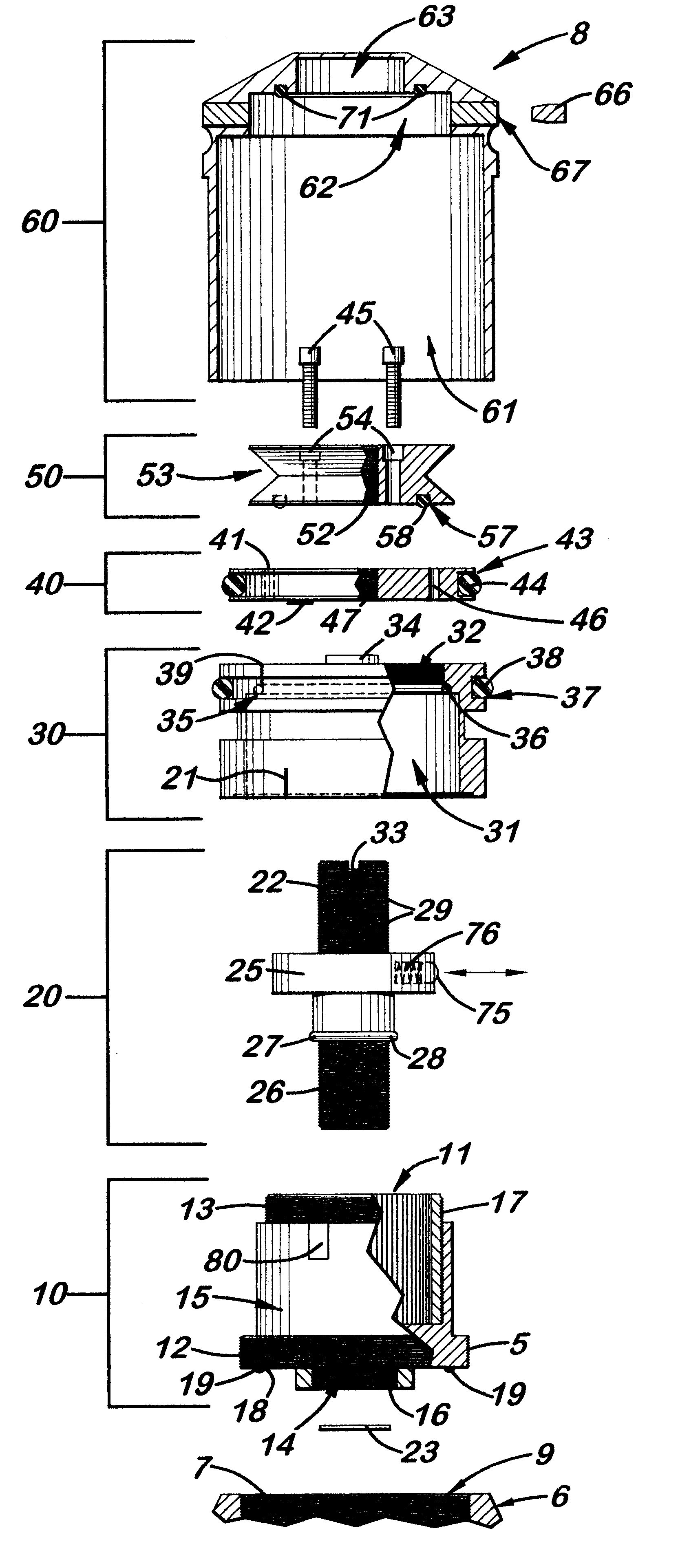
Referring to the accompanying Figs., there is shown and described an adjustable zero stop scope mechanism 8 for a riflescope that allows a user to establish the "zero point" at any point in the scope range, and still maintain 1 / 4 minute clicks and with unlimited rotations of the outer cap 60.

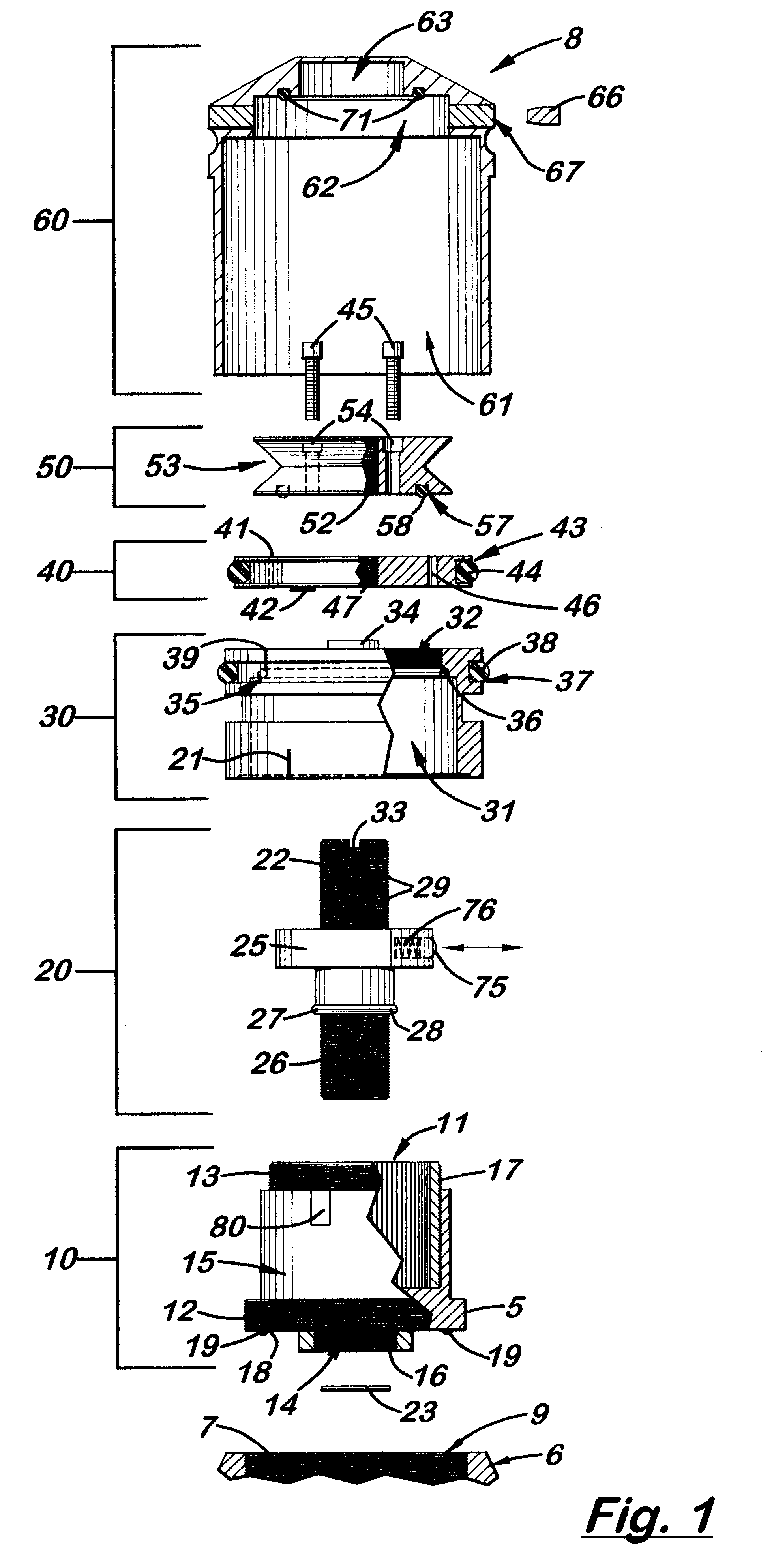
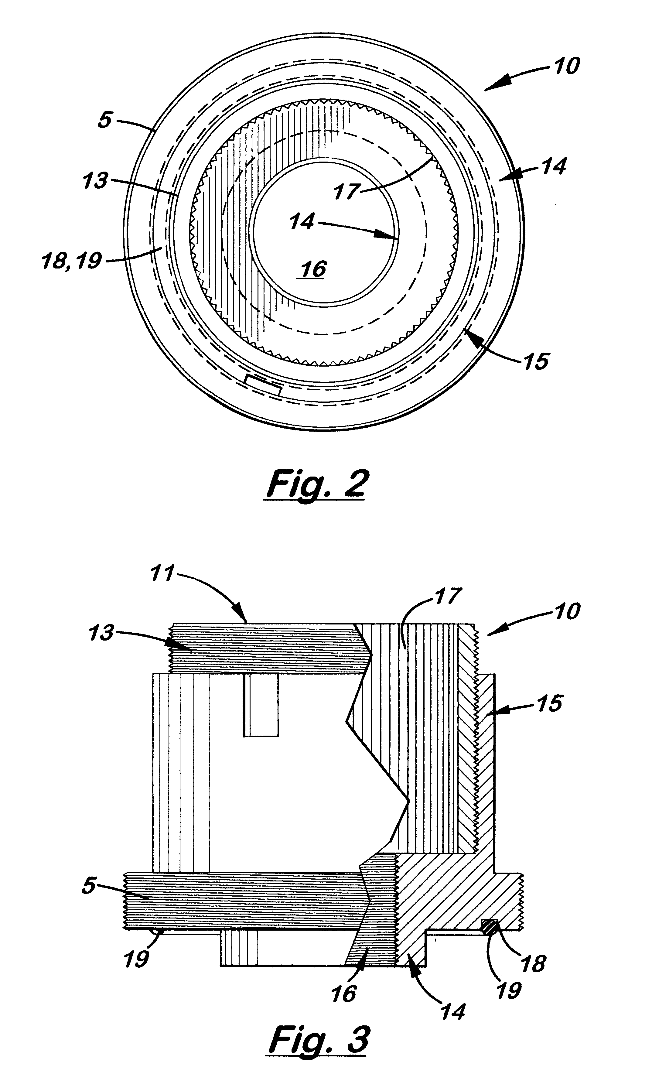
The mechanism 8 includes an adjustment bolt 20 vertically aligned inside a cylindrical-shaped adjustment body 10 that fits into a hole 9 formed on the turret 6 of a riflescope (not shown). The adjustment body 10, shown more clearly in FIGS. 1-3, is a cylindrical-shaped structure with a lower threaded base 12 and an upper section 15. Formed inside the upper section 15 is a central cavity 11. Extending downward from the threaded base 12 is a longitudinally aligned collar 14. Formed inside the collar 14 is a threaded bore 16. Formed inside the central cavity 11 is a plurality of longitudinally aligned splines 17, and formed on the lower surface of the threaded base 12 is an optional circular slot ...


PUM


Abstract

A "zero stop" rifle scope adjustment mechanism that allows a user to establish the "zero point" at any point in the scope range, and still maintain ¼ minute clicks and with unlimited rotations of the adjustment knob. The mechanism includes a T-shaped adjustment bolt that is vertically aligned inside an adjustment body fixed in position on the turret of the rifle scope. The adjustment body includes a small threaded central bore to which the adjustment bolt is attached. The adjustment body also includes an upward cavity with splines formed on the inside surface. When assembled, the threaded upper section of the adjacent bolt extends above the top surface of the adjustment body. Disposed longitudinally and locked in position over the threaded upper section of the adjustment bolt and around the adjustment body is an index dial. Attached to the threaded upper section that extends above the index dial is a stop ring and a lock ring that are selectively locked together on the upper section of the adjustment bolt. A tab element is formed on the top surface of the index dial body which is engaged by a complimentary-shaped tongue member of the stop ring which locks the index dial body and stop plate together to prevent further downward rotation of the stop plate over the body. An outer cap is then longitudinally aligned and inserted over the stop ring, lock ring, index dial, and the adjustment body. The outer cap includes locking screw which when tightened, is forced against the lock ring to lock the outer cap thereto.

Description

1. Field of the InventionThis invention relates to telescopic scopes used with firearms and, more particularly, to scopes that can be "zeroed-in" for more accurate long range shooting.2. Description of the Related ArtRiflescopes, telescopic scopes for rifles, are commonly used by hunters to aim their rifles at selected targets. During use, the hunter looks into the scope and positions the target within the field of view of the scope reticle. Because gravity causes the bullets to drop when they exit the rifle barrel, the angular position of the scope with respect to the rifle barrel must be compensated so that the impact point of the bullet matches the target seen on the scope reticle. The act of adjusting the angular position of the scope with respect to the rifle barrel is known as "zeroing-in".Typically, a scope is zeroed-in by the hunter when firing bullets at a target at a known distance. After viewing a group of impacts on the target, the hunter determines the distance of drop ...

Claims


Application Information

Patent Timeline
Patent Type & Authority Patents(United States)
IPC IPC(8): F41G1/38F41G1/00
CPCF41G1/38
Inventor HUBER, JEFFREY
Owner LIGHTFORCE USA
Why Eureka
Try Eureka