Spiral heat exchanger

Inactive Publication Date: 2003-11-11
ALFA LAVAL AB
View PDF20 Cites 22 Cited by
  • Summary
  • Abstract
  • Description
  • Claims
  • Application Information

AI Technical Summary

Problems solved by technology

In this known design, it is difficult to obtain a proper weld joining the central sheet to the inner surface the central pipe.
In the prior art heat exchangers the stiffeners and the holes of the central pipe cause clogging of the fibres or particles, which necessitates frequent dismounting and cleaning of the heat exchanger.
Also, a central pipe provided with openings is prone to erosion around the openings, especially if the heat exchange fluids contain fibres or particles.
Howeve

Method used


Image

  • Spiral heat exchanger
  • Spiral heat exchanger
  • Spiral heat exchanger

Examples


Embodiment Construction

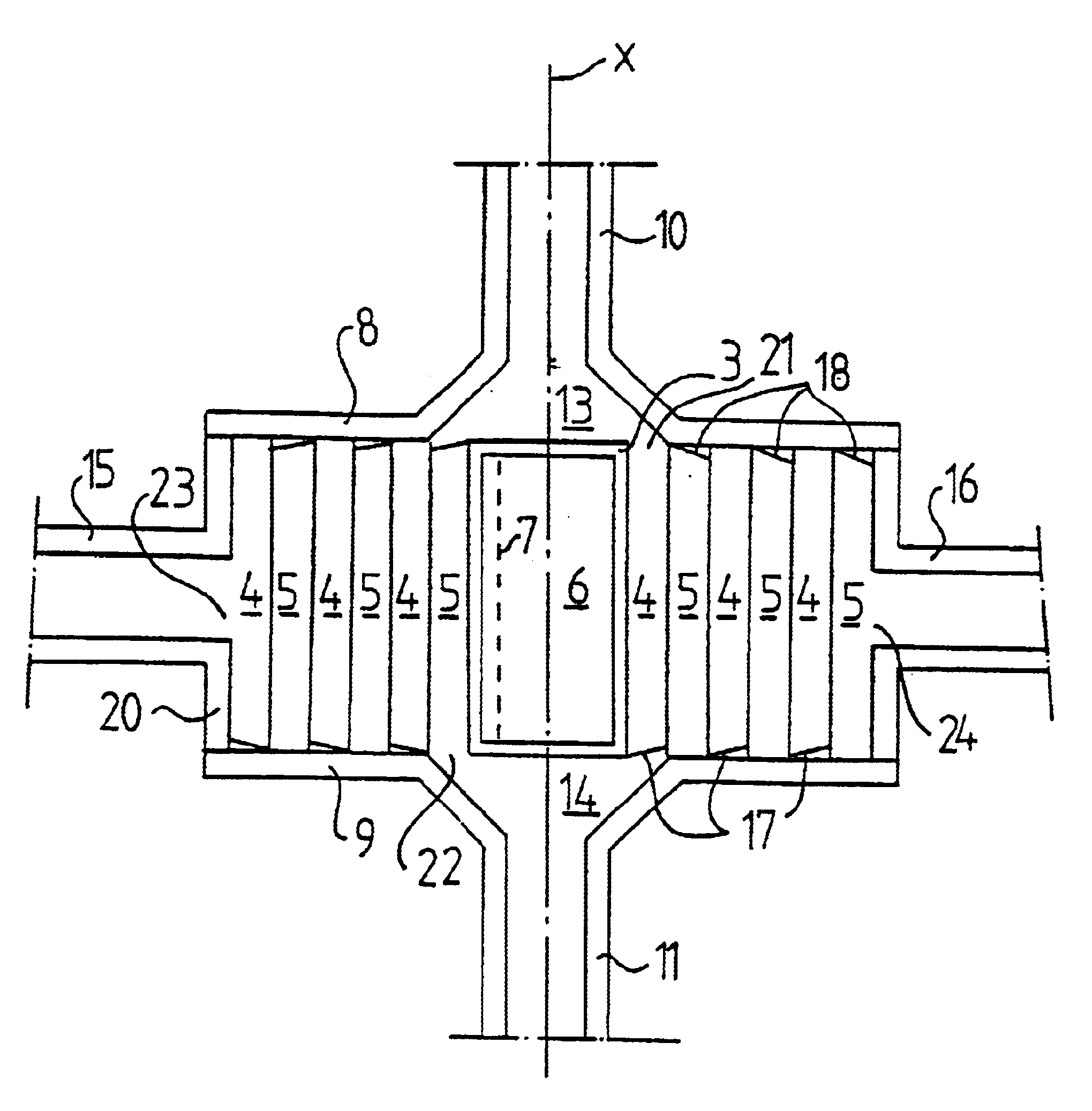
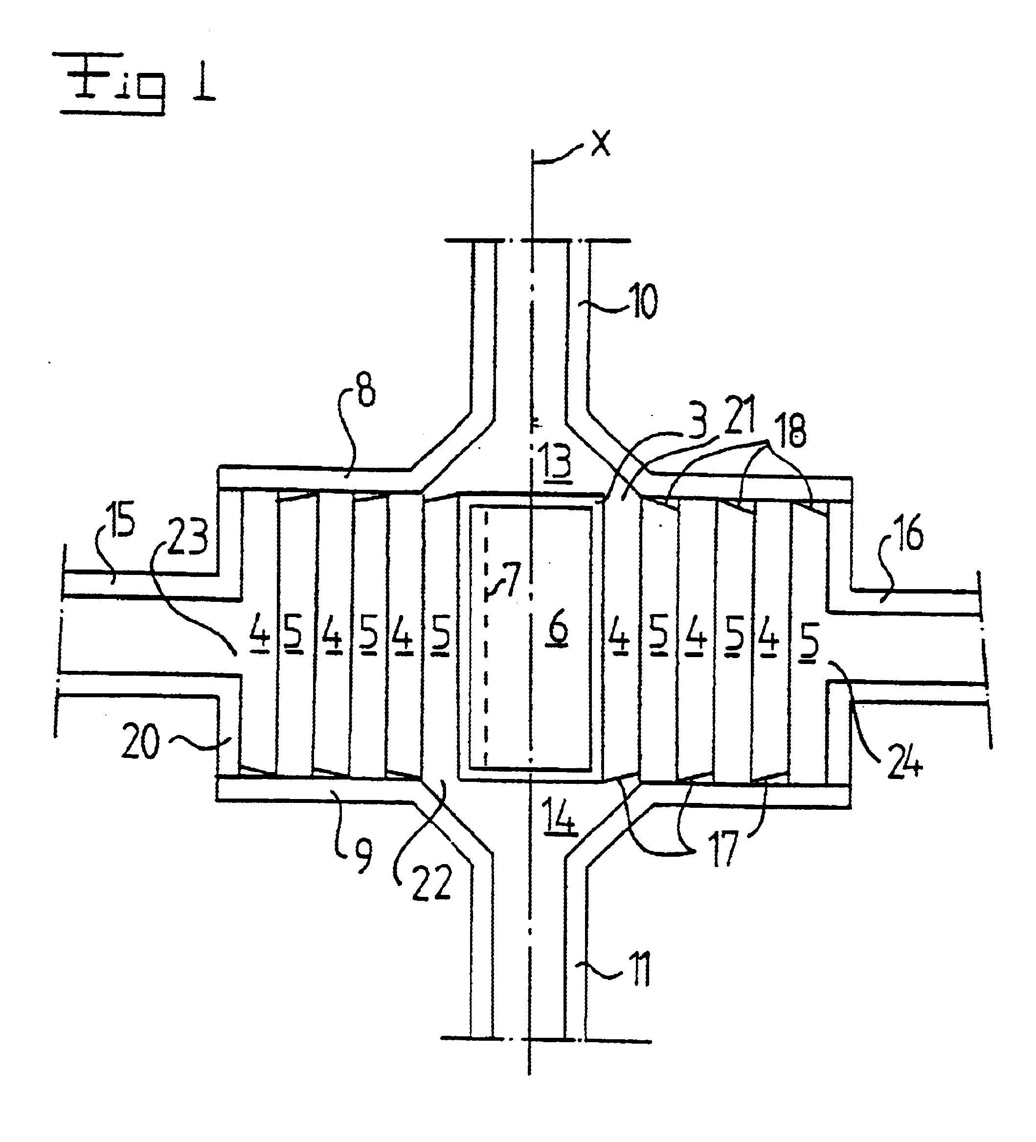
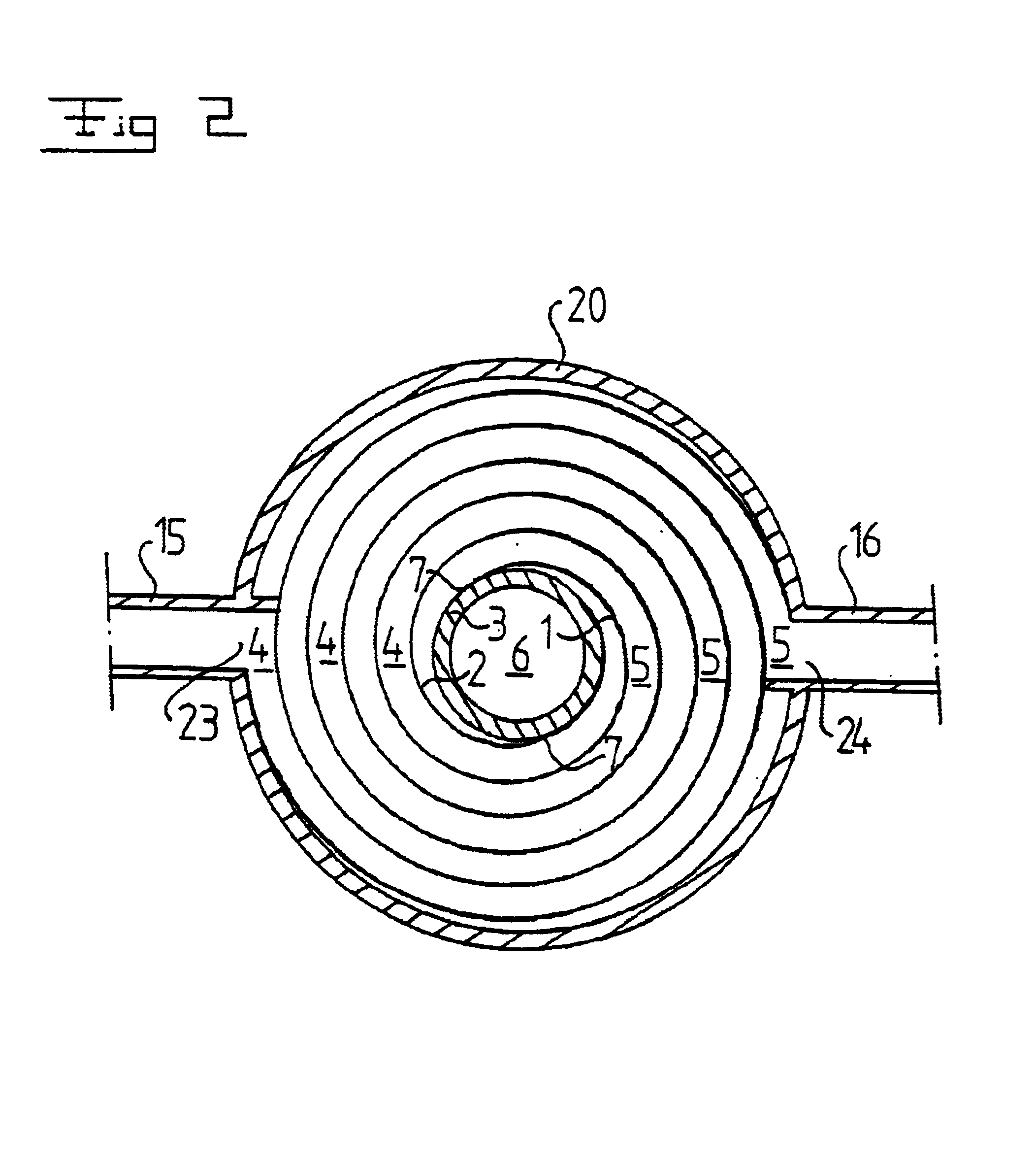
FIGS. 1 and 2 discloses schematically a first embodiment of the spiral heat exchanger according to the invention. The heat exchanger includes two spiral metal sheets 1, 2 extending along a respective spiral-shaped path around a common centre axis x. The two spiral metal sheets 1, 2 are joined to a centre body 3 along a respective line 7, which are substantially parallel to the centre axis x. The lines 7 are positioned diagonally opposite to each other with respect to the centre axis x as appears from FIG. 2. The centre body 3 has a mainly circular cylindrical shape with a substantially continuous outer surface to which the two spiral sheets 1, 2 are joined. The spiral metal sheets 1, 2 may be joined to the centre body 3 by a weld along the respective line 7, although other joining methods may be used.

The two spiral metal sheets 1, 2 form two spiral-shaped flow channels 4, 5, which are substantially parallel to each other. Each flow channel permits a heat exchange fluid to flow in a ...


PUM


Abstract

The invention relates to a spiral heat exchanger including at least two spiral sheets (1, 2) extending along a respective spiral-shaped path about a common center axis (x) and forming at least two spiral-shaped, substantially parallel flow channels (4, 5). Each flow channel (4, 5) permits a heat exchange fluid to flow in a substantially tangential direction with respect to the center axis (x). Each flow channel includes a radially outer orifice, which forms an outlet or an inlet of the respective flow channel and which is located at a radially outer part of the respective flow channel and a radially inner orifice, which enables communication between the respective flow channel and a respective inlet/outlet chamber (13, 14). The center axis (x) extends through the inlet/outlet chamber of the radially inner orifice. The spiral heat exchanger includes a center body (3) extending around the center axis (x) and being closed with respect to the flow channels (4, 5).

Description

BACKGROUND OF THE INVENTION AND PRIOR ARTThe present invention refers to a spiral heat exchanger including at least two spiral sheets extending along a respective spiral-shaped path around a common centre axis and forming at least two spiral-shaped flow channels, which are substantially parallel to each other, wherein each flow channel includes a radially outer orifice, which enables communication between the respective flow channel and a respective outlet / inlet conduit and which is located at a radially outer part of the respective flow channel with respect to the centre axis, and a radially inner orifice, which enables communication between the respective flow channel and a respective inlet / outlet chamber, so that each flow channel permits a heat exchange fluid to flow in a substantially tangential direction with respect to the centre axis, wherein the centre axis extends through the inlet / outlet chambers at the radially inner orifice.Such a spiral heat exchanger is disclosed in S...

Claims


Application Information

Patent Timeline
IPC IPC(8): F28D9/04F28D9/00
CPCF28D9/04
Inventor FOURT, OLIVIERMAUPETIT, PHILIPPE
Owner ALFA LAVAL AB
Why Eureka
Try Eureka