Clamping device having indirect driving mechanism

a technology of driving mechanism and clamping device, which is applied in the direction of clamps, vices, manufacturing tools, etc., can solve the problems of difficult to release the push rod, plate may not be easily assembled or engaged on the push rod, etc., and achieve the effect of reducing the volume of the clamping device and easy releasing the rod

Inactive Publication Date: 2003-11-18
LEE YUNG JEN
View PDF5 Cites 52 Cited by
  • Summary
  • Abstract
  • Description
  • Claims
  • Application Information

AI Technical Summary

Benefits of technology

The other objective of the present invention is to provide a clamping device including a slidable jaw attached onto the rod and movable toward the support for reducing the volume of the clamping device.
The further objective of the present invention is to provide a clamping device including a mechanism for easily releasing the rod.
The housing includes a first jaw provided thereon, the rod includes a second jaw provided thereon and movable toward the first jaw when the rod is moved relative to the housing. The housing is not required to provide any support structure to support the second jaw to the housing, such that the volume of the clamping device may be reduced.
A ring may further be provided and engaged onto the rod and engaged between the catch plate and the second biasing means, for preventing the second biasing means from biasing against the catch plate.

Problems solved by technology

In addition, the plate may not be easily assembled or engaged onto the push rod.
However, it will be difficult to release the push rod.

Method used


Image

  • Clamping device having indirect driving mechanism
  • Clamping device having indirect driving mechanism
  • Clamping device having indirect driving mechanism

Examples


Embodiment Construction

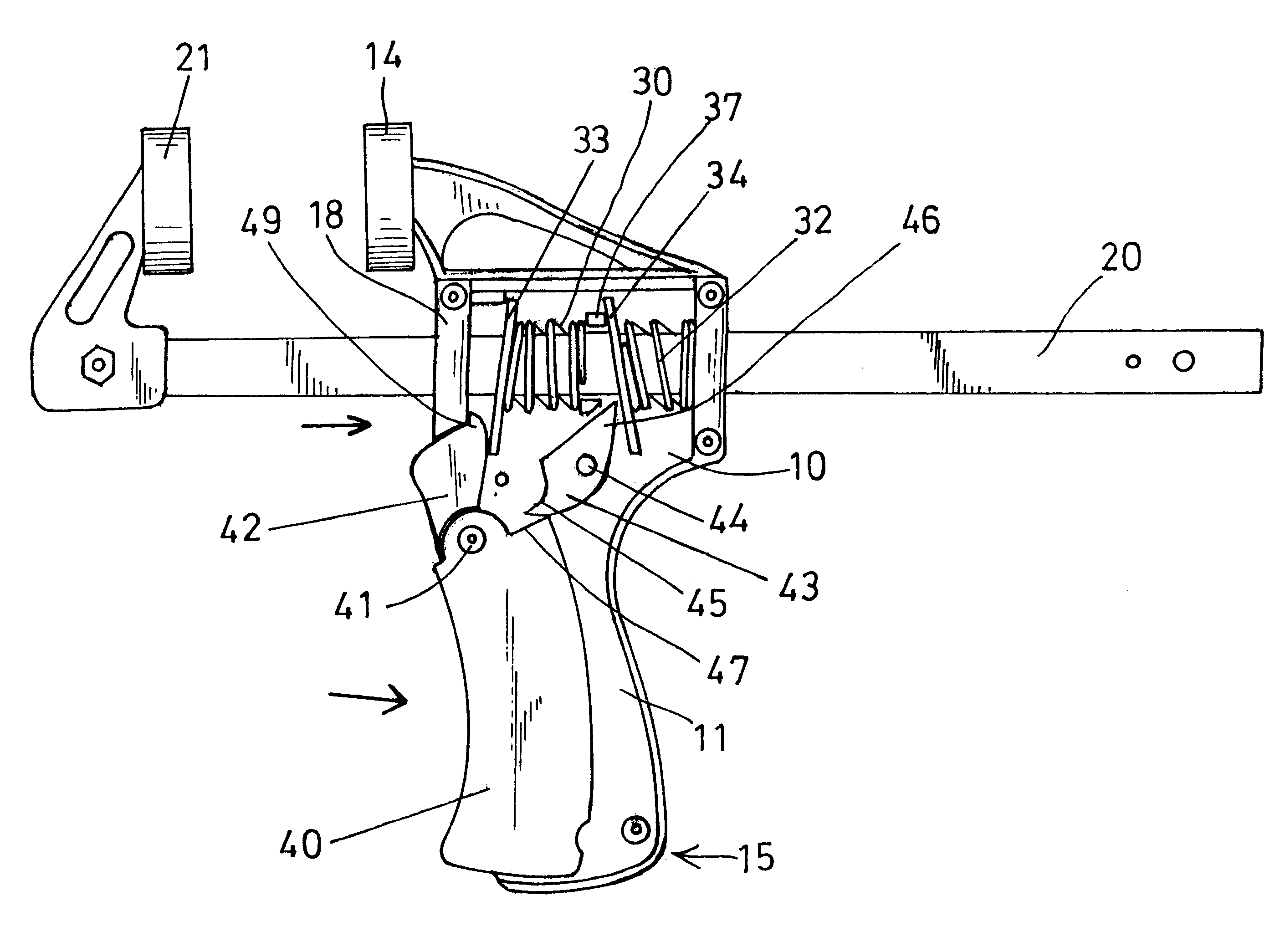
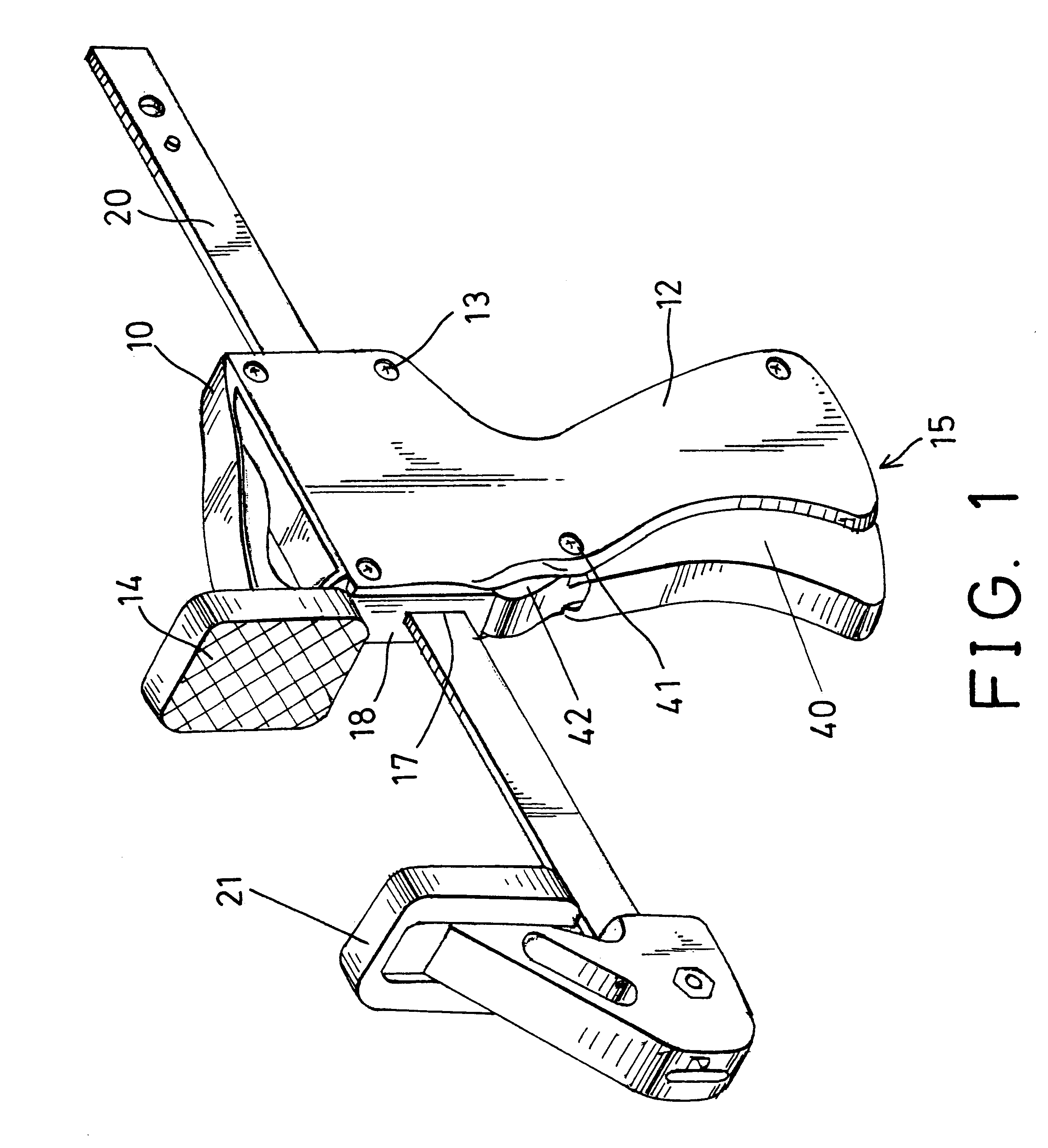
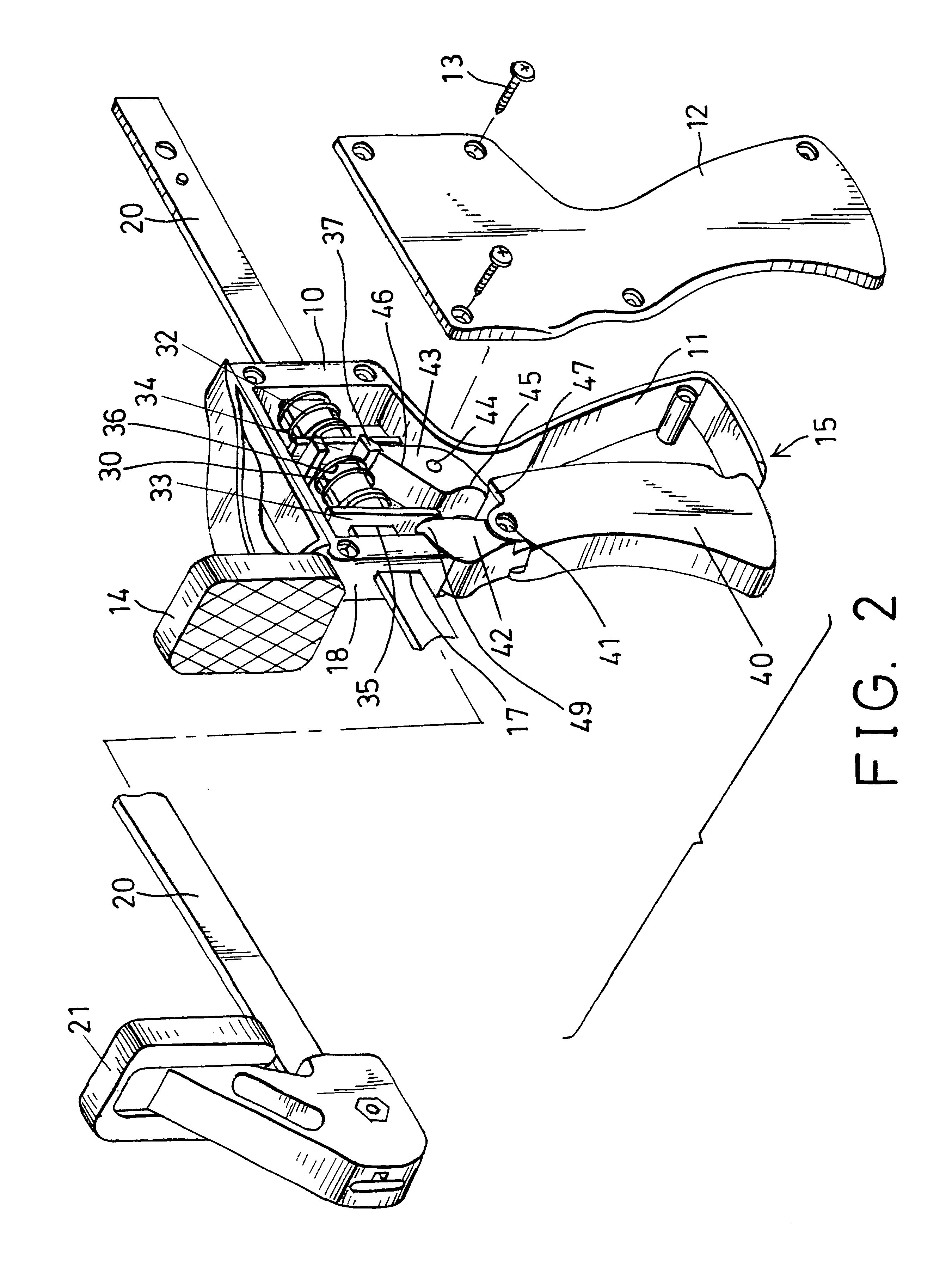
Referring to the drawings, and initially to FIGS. 1-3, a clamping device in accordance with the present invention comprises a support body or a housing 10 including a chamber 11 formed therein, a cover 12 detachably secured to the housing 10 with such as fasteners 13, for enclosing the chamber 11.

The housing 10 includes a fixed jaw 14 provided or formed on top thereof, and includes a handle 15 formed or provided on the lower portion thereof, and includes a channel 17 laterally formed in the upper portion thereof.

A push rod or a rack or a rod 20 is slidably received in the channel 17 of the housing 10, and includes another jaw 21 secured on one end thereof, such as the front end thereof, and movable toward and away from the fixed jaw 14 when the rod 20 is moved relative to the housing 10.

Two springs 30, 32, such as the coil springs 30, 32 are movably or slidably engaged onto the rod 20 and received in the chamber 11 of the housing 10. A release panel 33 and a catch plate 34 are recei...


PUM


Abstract

A clamping device includes a rod slidably received in a channel of a housing, a catch plate and a release panel slidably engaged onto the rod and biased to be released and engaged onto the rod. A hand grip is pivotally secured to the housing, a pawl is rotatably secured in the housing and has one end engageable with the hand grip and the other end engageable with the catch plate to tilt the catch plate relative to the rod and for allowing the rod to be moved relative to the housing by the hand grip and the pawl. A knob may move and release the release panel relative to the rod.

Description

BACKGROUND OF THE INVENTION1. Field of the InventionThe present invention relates to a clamping device, and more particularly to a clamping device having an indirect driving mechanism.2. Description of the Prior ArtVarious kinds of typical clamping devices, particularly the C-shaped clamping devices have been developed for dispensing various materials that are received in cylindrical receptacles or cartridges.U.S. Pat. No. 5,156,305 to Eyre discloses one of the typical clamping devices having a supporting member for supporting the cylindrical receptacles or cartridges therein, and a rack or push rod advanceable along the supporting member. A handle is pivotally secured to the supporting member and has a plate engaged onto the push rod for moving the push rod forwardly step by step by pulling or forcing the handle toward the supporting member.However, the plate is directly attached onto the handle and may be disengaged from push rod right away at the moment when the handle is pulled ...

Claims


Application Information

Patent Timeline
Patent Type & Authority Patents(United States)
IPC IPC(8): B25B5/06B25B5/00
CPCB25B5/068
Inventor LEE, YUNG JEN
Owner LEE YUNG JEN
Why Eureka
Try Eureka