
Ferroelectric liquid crystal display and fabricating method thereof

a liquid crystal display and ferroelectric technology, applied in the field of ferroelectric liquid crystal display, can solve the problems of destroying alignment, difficult to achieve, and destroying alignment, and achieve the effect of light sensitiv

Inactive Publication Date: 2003-12-02
LG DISPLAY CO LTD
View PDF8 Cites 34 Cited by
  • Summary
  • Abstract
  • Description
  • Claims
  • Application Information

AI Technical Summary

Benefits of technology

The solution achieves reduced flicker and improved alignment stability, allowing the display to be driven by both positive and negative electric fields, enhancing picture quality and enabling re-alignment through heat treatment, thus overcoming the limitations of conventional FLC displays.

Problems solved by technology

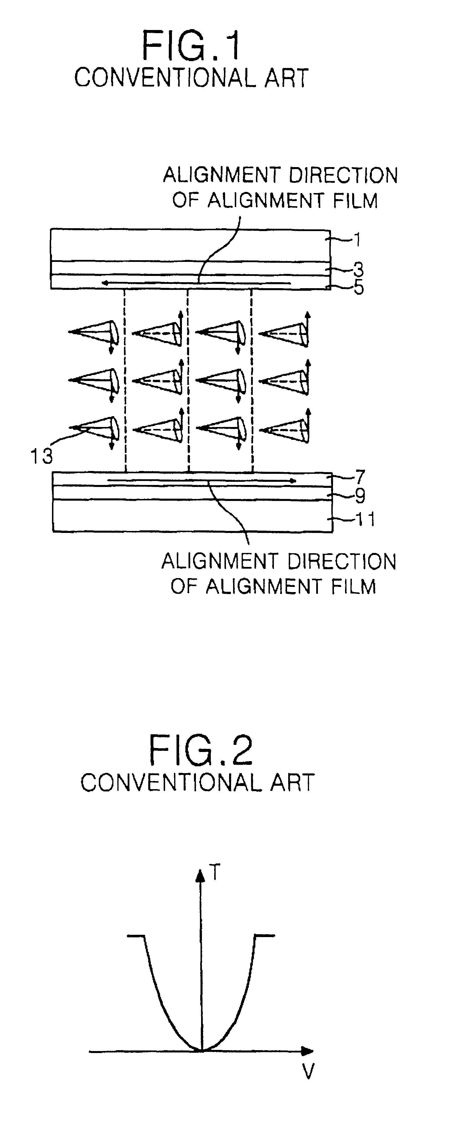
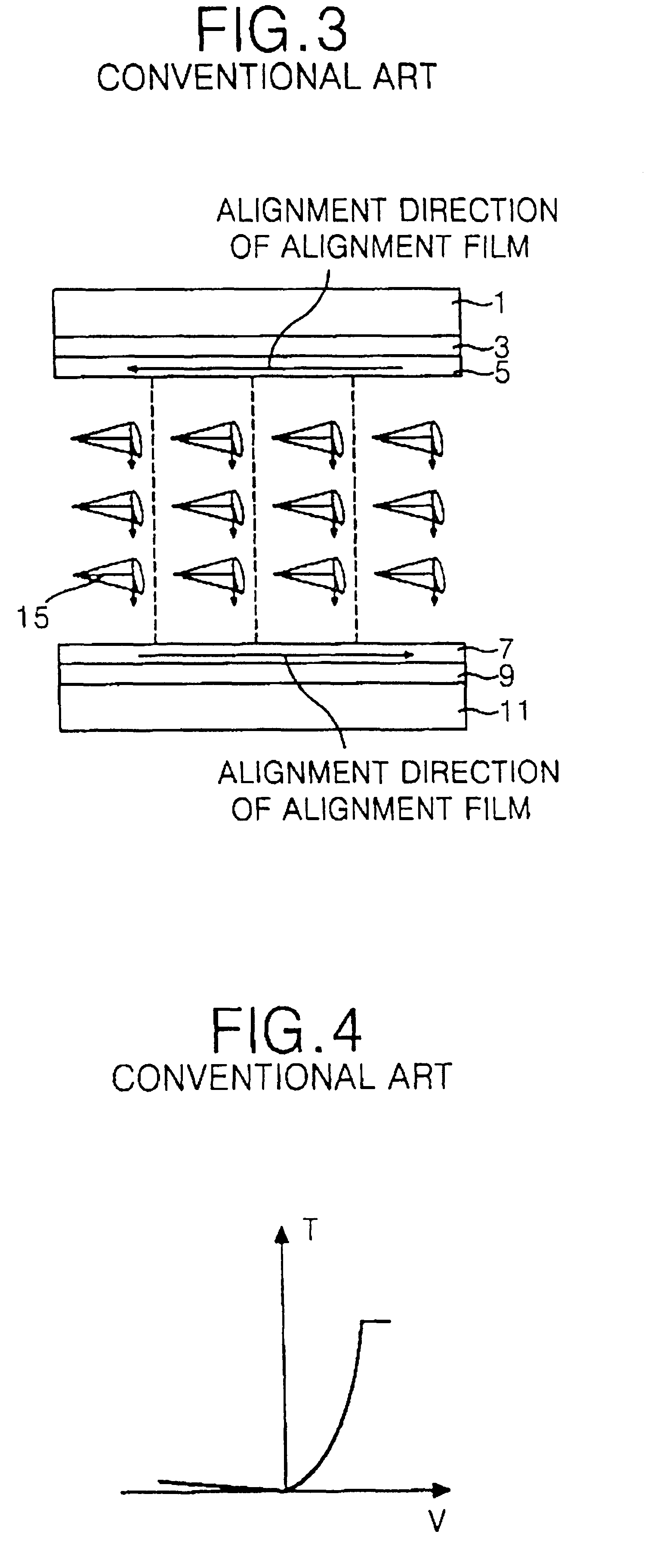
However, such a liquid crystal cell has a problem in that breaking the initial alignment, such as by external impacts that are inevitably applied by grinding a shorting bar, destroys that alignment.
However, this is difficult to do once the shorting bar, which was used for applying the electric fields, is removed.
In addition to shock, heating a conventional half V-mode FLC liquid crystal cell can destroy the alignment.
However, this scheme is complex to implement, particularly with high brightness.
However, this requires development of a novel driver IC, and thus increases cost.
As a result, it becomes difficult to achieve equal alignment forces on the upper alignment film and on the lower alignment film.
Furthermore, because of problems with achieving uniform alignment, the FLC liquid crystal cell illustrated in FIG. 7 has proven difficult to mass produce, particularly in large dimension LCDs.

Method used


Image

  • Ferroelectric liquid crystal display and fabricating method thereof
  • Ferroelectric liquid crystal display and fabricating method thereof
  • Ferroelectric liquid crystal display and fabricating method thereof

Examples


Embodiment Construction

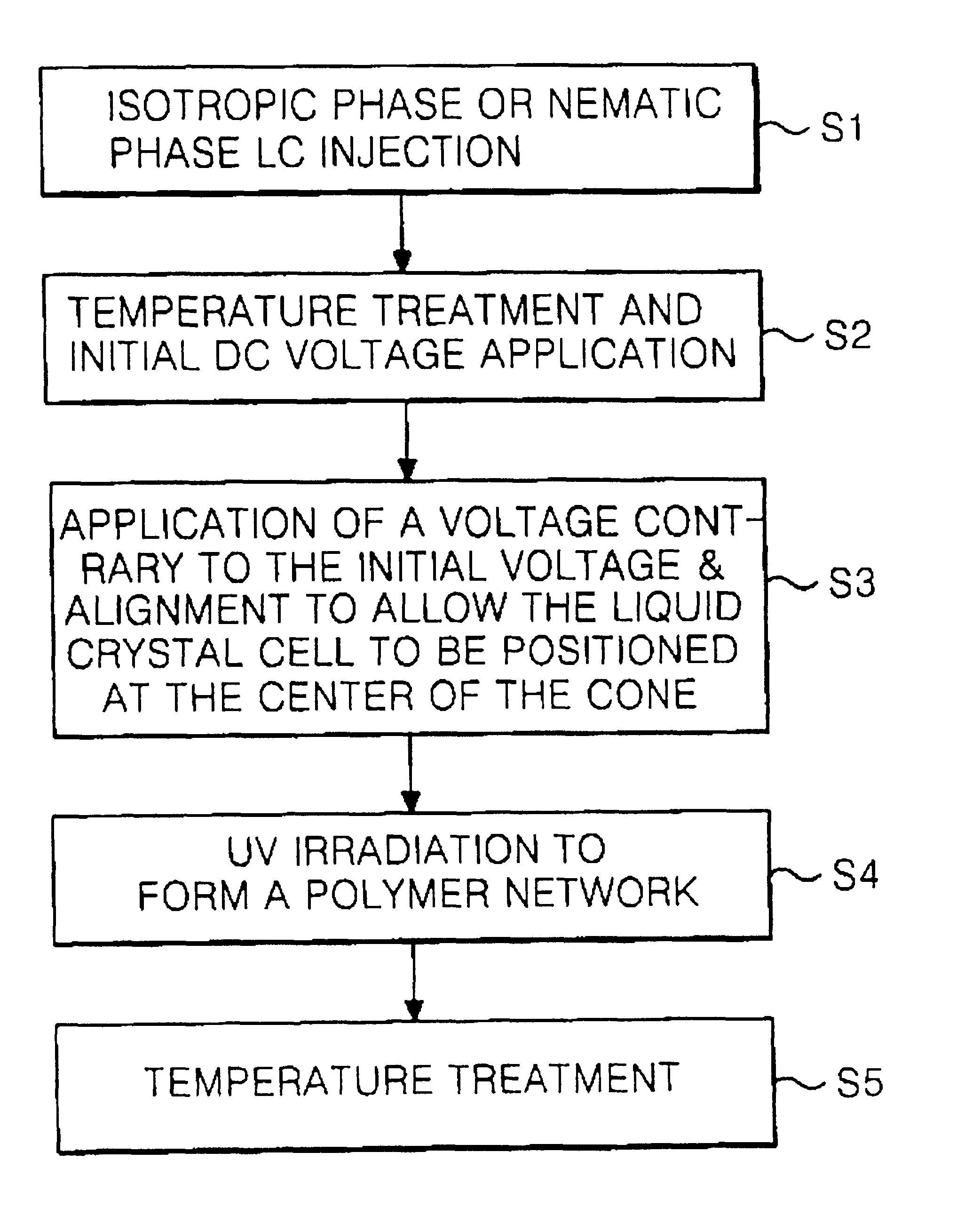
FIGS. 9A to 9C and FIG. 10 illustrate fabricating an FLC liquid crystal cell according to an embodiment of the present invention. In FIG. 9A, the FLC mode liquid crystal cell includes an upper substrate 21 having a color filter layer (not shown), a common electrode 23, and an alignment film 25 that are sequentially disposed. That FLC liquid crystal cell also includes a lower substrate 31 having a thin film transistor (TFT) array 29 and an alignment 27. The thin film transistor (TFT) array 29 includes a plurality of pixel electrodes. After the upper substrate 21 and the lower substrate 31 are joined, a ferroelectric liquid crystal 33, which contains a small amount of a light-cured monomer 35, is injected between the upper substrate 21 and the lower substrate 31. Beneficially, the ferroelectric liquid crystal 33 is injected in the dark.

Referring now to FIG. 10, in a step S1 the ferroelectric liquid crystal 33 is maintained during injection at a temperature at which the liquid crystal ...


PUM

PropertyMeasurementUnit
ferroelectricaaaaaaaaaa
DC voltageaaaaaaaaaa
temperatureaaaaaaaaaa

Abstract

A liquid crystal display cell, and a fabricating method thereof, that incorporates a light-cured monomer in a ferroelectric liquid crystal. By injecting the light-cured monomer / ferroelectric liquid crystal between substrate while in a nematic phase or isotropic phase, by performing DC voltage treatments as the liquid crystal temperature decreases, and by performing a light irradiation treatment, a stable, aligned ferroelectric liquid crystal cell is produced. Such a ferroelectric liquid crystal cell can reduce flicker and can be realigned after a physical shock.

Description

CROSS REFERENCEThis application claims the benefit of Korean Patent Application No. P2000-86963, filed Dec. 30, 2000, under 35 U.S.C. .sctn.119, the entirety of which is hereby incorporated by reference.1. Field of the InventionThis invention relates to a liquid crystal display, and more particularly to a ferroelectric liquid crystal display having reduced flicker and a stable liquid crystal alignment.2. Description of the Related ArtA liquid crystal display (LCD) controls the light characteristics of a display screen so as to produce a desired image. Liquid crystals used in liquid crystal displays are in a neutral state between a liquid and a solid. That neutral state has both fluidity and elasticity.While there are many types of liquid crystals, one type of great interest is the smectic C liquid crystal. During a thermodynamic phase transition, smectic C liquid crystal molecules rotate along an outer line of a virtual cone. Such a smectic C phase liquid crystal can undergo a spont...

Claims


Application Information

Patent Timeline
Patent Type & Authority Patents(United States)
IPC IPC(8): G02F1/13G02F1/141G02F1/137
CPCG02F1/141G02F2001/13775G02F1/13775
Inventor CHOI, SU SEOK
Owner LG DISPLAY CO LTD
Learn More