Reflection-type ferroelectric liquid crystal display

A liquid crystal display, ferroelectric liquid crystal technology, applied in the field of reflective liquid crystal displays, can solve the problems of changing electro-optical characteristics, image defects, ghosting, etc.

Inactive Publication Date: 2004-02-25
ROLIC AG
View PDF2 Cites 0 Cited by
  • Summary
  • Abstract
  • Description
  • Claims
  • Application Information

AI Technical Summary

Problems solved by technology

In effect, these space charges alter the electro-optic p

Method used


Image

  • Reflection-type ferroelectric liquid crystal display
  • Reflection-type ferroelectric liquid crystal display
  • Reflection-type ferroelectric liquid crystal display

Examples


Embodiment Construction

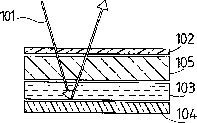
[0035] Such as Figure 4 As shown, the traditional light-transmitting DHF unit 201 has a layer of S with thickness d C * Layer 202, which is arranged between two mutually parallel sheets of transparent material 203 and 204. Suitable transparent materials for the parallel sheets 203 and 204 are, for example, glass, acrylic glass or plastic films.

[0036]The polarizer 205 is located on the outside of the upper layer 203, and is preferably connected to the layer 203, for example, glued together with the layer. Correspondingly, a polarizer 206 is similarly assigned to the lower layer 204, which in the embodiment shown acts as an analyzer when light is incident from above and passes through the cell. In the reflective cell configuration, the second polarizer 206 is not required. If light is incident from below, the first polarizer 205 is not needed. Instead of the omitted polarizer, unit 201 has a light reflector or a diffuse reflector.

[0037] The liquid crystal layer 202 ...


PUM

PropertyMeasurementUnit
Rotation angleaaaaaaaaaa

Abstract

The invention relates to a novel reflective, ferroelectric display which can be actuated without DC voltage and has a maximum switching angle alpha which is +-22.5 DEG C. The liquid crystal display according to the invention is distinguished in particular by the fact that a further birefringent element is arranged between the two plates bounding the birefringent liquid crystal layer. In a first category of liquid crystal displays according to the invention, this additional birefringent element is a transparent plate having an optical path difference DELTAn.d PRG lambd/4, which is arranged after the liquid crystal layer in the direction of the light incidence, in particular between said layer and the mirror.

Description

technical field [0001] The invention relates to a reflective liquid crystal display with a ferroelectric and chiral smectic liquid crystal layer. [0002] The invention also relates to a projection system and a direct-view display having a liquid crystal display of the type described above. Background technique [0003] The display according to the invention has, for example, a birefringent liquid crystal layer (hereinafter also referred to as S C * layer). [0004] EP-B-0309774 discloses a known deformed liquid crystal display based on a helical liquid crystal configuration. For example, the display disclosed in this document, also known as a DHF cell (DHF stands for Deformed Helical Ferroelectric), has a pair of transparent sheets which together surround the S C * layer, and each slice has such that S C * A molecularly oriented surface structure of the layer, with electrodes for generating an electric field in the liquid crystal, and with polarizers. [0005] The l...

Claims


Application Information

Patent Timeline
IPC IPC(8): G02F1/1335G02F1/136G02F1/1368G02F1/141
CPCG02F1/141G02F1/133553G02F1/133634G02F1/1393G02F1/1396
Inventor 朱尔德·芬希林马丁·谢德特
Owner ROLIC AG
Why Eureka
Try Eureka