Stand-up bag

a stand-up bag and bag body technology, applied in the field of stand-up bags, can solve the problems of difficult opening and increase the cost of bags, and achieve the effect of simple and inexpensive manufacturing, easy opening and opening toolless

Inactive Publication Date: 2003-12-09
AMCOR FLEXIBLES EURO
View PDF14 Cites 92 Cited by
  • Summary
  • Abstract
  • Description
  • Claims
  • Application Information

AI Technical Summary

Benefits of technology

The object of the invention is to provide a stand-up bag of the above type which is easy to open toollessly and which is simple and inexpensive to manufacture.
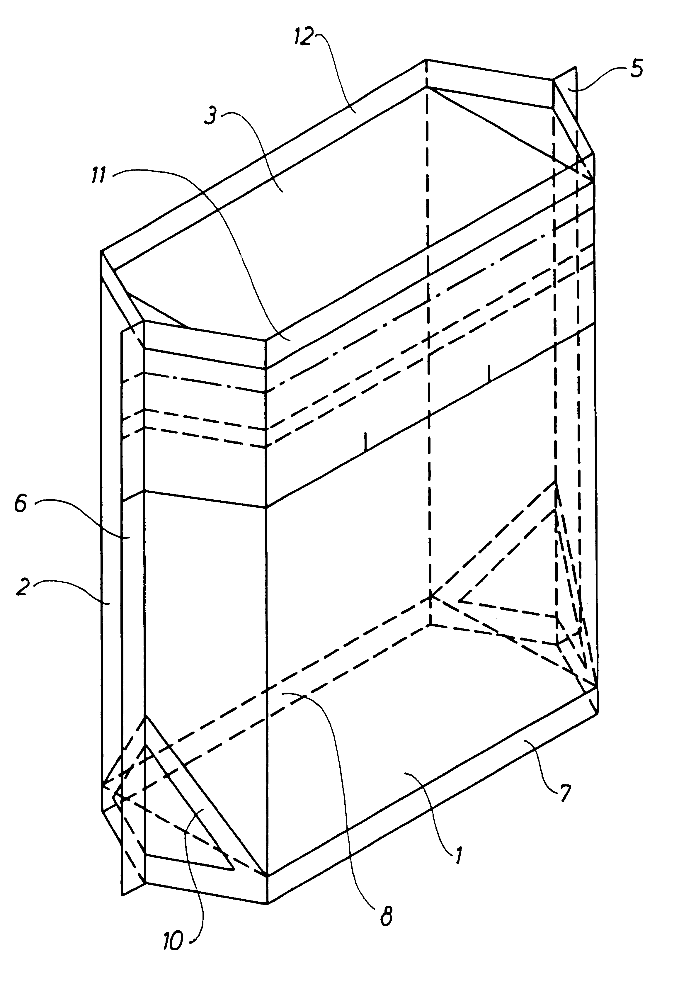
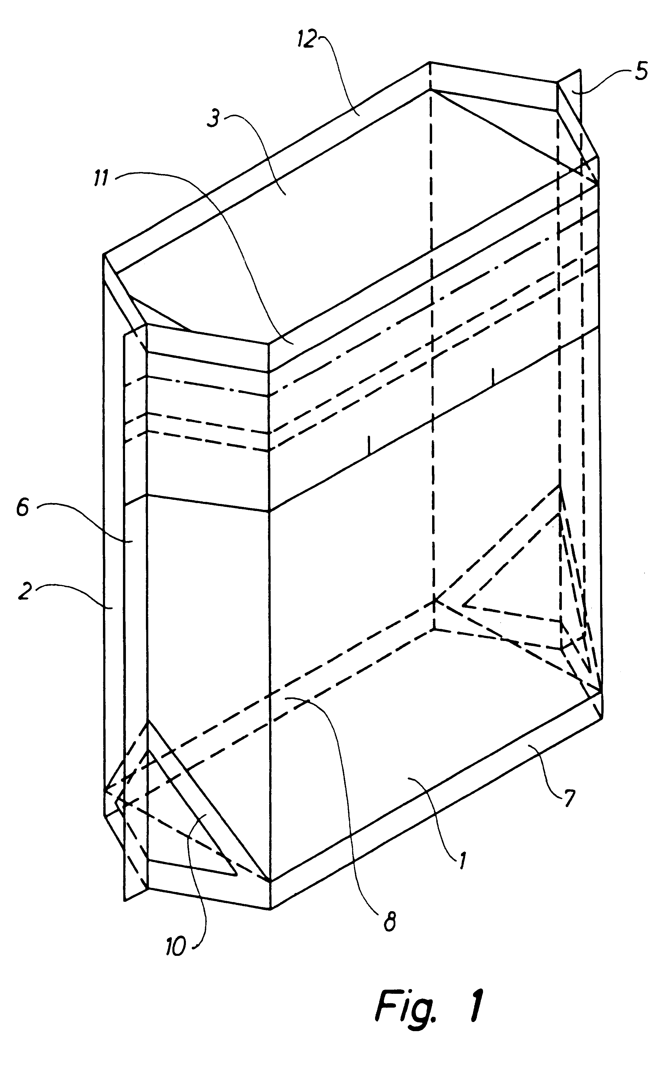
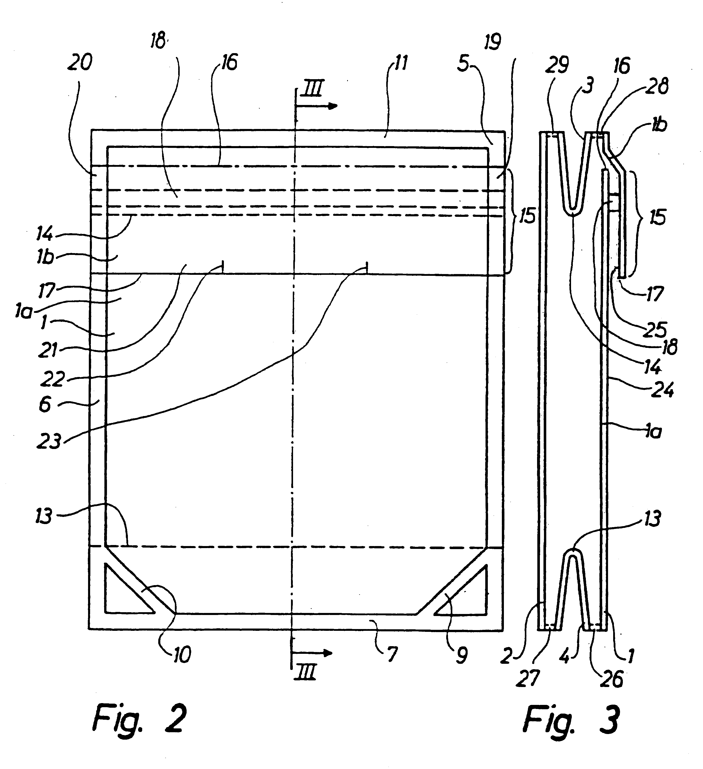
The stand-up bag according to the invention is characterised in that one side wall comprises a first side wall section and a second side wall section overlapping the first side wall section in a transverse overlapping area between transverse edges of the two side wall sections, that the side wall sections in the overlapping area are connected by means of longitudinal peelable connections along the side seams and by means of a transverse peelable connection, and that the second side wall section extends beyond the transverse peelable connection to form a gripping member. The bag is thus easy to open by gripping and pulling the gripping member, whereby the transverse peelable connection and the longitudinal peelable connections are broken.
The above embodiment further makes it possible to provide the bag with a degree of reclosability when a pressure-sensitive adhesive, eg. an adhesive of the hot-melt type, is used as the intermediate layer. As the intermediate layer--as mentioned above--is exposed when opening the peelable connections of the bag and the intermediate layer is of a self-sealing adhesive, after the initial opening of the bag said layer is able to adhere to the surface of the opposed side wall section.

Problems solved by technology

It is however considered a drawback of the known stand-up bags that they are difficult to open why a pair of scissors or a knife is often needed or--as for instance known from WO 93 / 16928 and EP-A-2.0380.110--they are provided with special discharging arrangements for easy removal of the product which makes the bag more expensive.

Method used


Image

  • Stand-up bag
  • Stand-up bag
  • Stand-up bag

Examples


first embodiment

Having described above with reference to FIGS. 1 to 3 the peelable connections 18, 19, 20 in the overlapping area 15 between the upper side wall section 1b and the lower side wall section 1a reference is made to FIG. 3A embodiment of the peelable connections between the upper side wall section 1b and the lower side section 1a, however, only the transverse peelable connection 38 being shown. These peelable connections are formed of a hot-melt strip 30 applied to the inner surface 25 of the upper side wall section 1b in the overlapping area between the two side wall sections 1b and 1a. By activating the hot-melt by means of the sealing tools the peelable connection 38 is formed between the side wall sections 1a and 1b in the sealing zone 38 in a width corresponding to the width of the sealing tools used. In this embodiment of the peelable connections all of the above laminates may of course be used for the walls. However since the hot-melt strip 30 per se provides the intended peelabl...

third embodiment

FIG. 4 illustrates the peelable connections between the upper side wall section 1b and the lower side wall section 1a, however only the transverse peelable connection 48 being shown. The said peelable connections and specifically the transverse peelable connection 48 comprises a film strip 50 provided in the overlapping area 15 of the side wall sections 1a, 1b and sealed to the upper side wall section 1b by means of a strong seal and sealed to the lower side wall section 1a by means of a peelable seal. This feature is obtained by the strip 50 comprising a first surface 51 facing the upper side wall section 1b and being formed of a sealing medium layer corresponding substantially to the sealing medium layer forming the inner surface 25 of the upper side wall section 1b and further comprising a second surface 52 facing the lower side wall section 1b and being formed of a sealing medium sealing layer peelably by heat sealing to the sealing medium layer forming the outer surface 24 of t...

fourth embodiment

FIG. 5 illustrates the peelable connections in the overlapping area between the upper side wall section 1b and the lower side wall section 1a. These peelable connections, of which only the transverse peelable connection 58 appear from FIG. 5, comprise a film strip 60 arranged in the overlapping area 15 and having a first surface layer 61 and a second surface layer 62 of a sealing medium corresponding to the sealing medium forming the inner surface 25 of the upper side wall section 1b and the sealing medium layer forming the outer surface 24 of the lower side wall section 1a, said film strip thus being heat-sealed non-peelably to the said surfaces. An intermediate layer 63 is provided between the two surface layers 61 and 62 being connected peelably to the second surface layer 62 and preferably more firmly connected to the first surface layer 61. The tear resistance of the second surface layer 62 is further weaker than the peel strength between said layer and the intermediate layer 6...


PUM

PropertyMeasurementUnit
heat-sealableaaaaaaaaaa
weldableaaaaaaaaaa
tear resistanceaaaaaaaaaa

Abstract

A stand-up bag of a heat-sealable plastic film comprising two opposing side walls (1, 2) sealed together along the lateral edges thereof by means of side seams (5, 6), an inwardly folded bottom wall (4) provided between the lower portions of the side walls (1, 2) and sealed to the respective side walls (1, 2) along transverse bottom seams (7) and along bottom side seams, and an inwardly folded top wall (3) extending between the side walls and connected to the respective side walls (1, 2) along transverse top connections (11, 12) and sealed to the respective side walls (1, 2) along top side seams. One of the side walls (1) comprises a first side wall section (1a) and a second side wall section (1b) which overlaps the first side wall section (1a) in an overlapping area (15). In the overlapping area (15) the two side wall sections (1a, 1b) are connected by means of longitudinal peelable connections (19, 20) along the side seams (5, 6) and by means of a transverse peelable connection (18). The second side wall section (1b) extends a distance past the transverse peelable connection (18) to form a gripping member (21).

Description

TECHNICAL FIELDThe invention relates to a stand-up bag of a heat-sealable or weldable plastic film for containing in particular flowable or pourable products and comprising: two opposing side walls sealed together along lateral edges thereof by means of side seams; an inwardly folded bottom wall extending between the lower portions of the side walls and sealed to the respective side walls along transverse bottom seams and along bottom side seams; and an inwardly folded top wall extending between the upper portions of the side walls and connected to the respective side walls along transverse top connections and sealed to the respective side walls along top seams.BACKGROUND ARTStand-up bags of this type are known inter alia from U.S. Pat. No. 3,935,993 and DE-A-2553853. Due their excellent standing properties and stability the bags have been used for a wide range of products, in particular for liquid, paste-like, powdery and granular products. It is however considered a drawback of th...

Claims


Application Information

Patent Timeline
Patent Type & Authority Patents(United States)
IPC IPC(8): B65D75/52B65D75/00B65D75/58B65D30/16B65D75/60B65D33/36
CPCB65D75/5855B65D75/008
Inventor SCHULZ, WERNER
Owner AMCOR FLEXIBLES EURO
Why Eureka
Try Eureka