Multifunction antenna for wireless and telematic applications

a multi-functional, printed technology, applied in the direction of resonant antennas, separate antenna unit combinations, radiating element structural forms, etc., can solve the problem of sharp reduction of bandwidth

Inactive Publication Date: 2003-12-16
EMAG TECH
View PDF35 Cites 90 Cited by
  • Summary
  • Abstract
  • Description
  • Claims
  • Application Information

AI Technical Summary

Problems solved by technology

However, bending the antenna element 22 immediately results in a sharp reduction of its bandwidth.
One of the current design challenges for making multifunction antennas includes providing a plurality of different antenna elements in a single compact structure.
Combining so many antennas in a single structure provides various design challenges that have heretofore not been met in the art.
One design challenge includes making some of the antennas, such as the GPS and the satellite radio antennas, circularly polarized with an upward looking beam to accommodate signals from satellites.

Method used


Image

  • Multifunction antenna for wireless and telematic applications
  • Multifunction antenna for wireless and telematic applications
  • Multifunction antenna for wireless and telematic applications

Examples


Embodiment Construction

The following discussion of the embodiments of the invention directed to a multifunction antenna for wireless and telematic applications is merely exemplary in nature, and is in no way intended to limit the invention or its applications or uses.

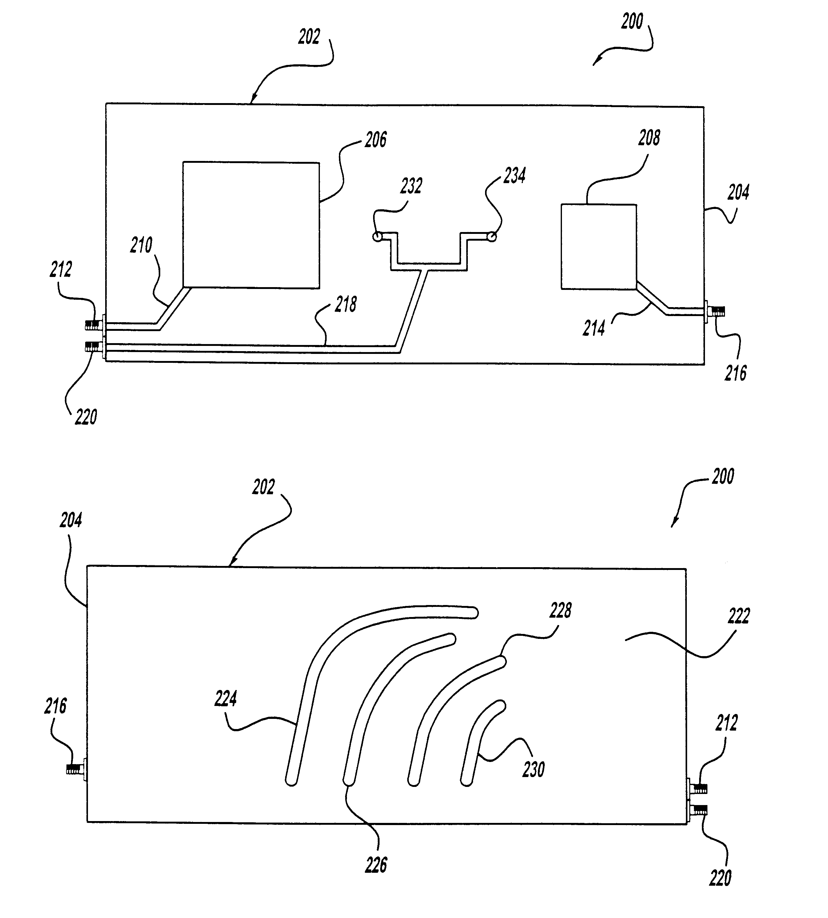
To overcome the limitations of reduced bandwidth for a curved or wound antenna design, the present invention proposes a multi-trace antenna design consisting of two or more slot antenna elements of different lengths configured in a relatively parallel orientation. FIG. 4 is a plan view of a printed antenna 30 having such a design, where the printed circuit board is removed for clarity. The antenna 30 includes two wound, resonating slot antenna elements 32 and 34 that represent slots etched in a ground plane, such as the ground plane 16, formed on a printed circuit board, such as the printed circuit board 14. A feed line 36, that is a conductive microstrip patterned on an opposite surface of the printed circuit board, includes a feed stub 38 t...


PUM


Abstract

A multifunction printed antenna for wireless and telematic applications. In one embodiment, GPS and satellite radio patch antenna elements are printed on one side of a printed circuit board and AMPS, PCS, GSM and terrestrial radio slot antenna elements are etched in a ground plane on an opposite side of the same printed circuit board. In an alternate embodiment, the GPS and satellite radio patch antenna elements are elements mounted on one printed circuit board and the AMPS, GSM, PCS and terrestrial radio slot antenna elements are etched in a ground plane on another printed circuit board rigidly secured orthogonal to the GPS and satellite printed circuit board. The AMPS, GSM and PCS circuit board can be curved to reduce the nulls at the edges of the circuit board. Further, the edge of the AMPS, GSM and PCS circuit board that contacts the GPS and satellite radio circuit board can have a saw-tooth pattern so that edge currents are reduced.

Description

1. Field of the InventionThis invention relates generally to a multifunction printed antenna and, more particularly, to a multifunction printed antenna for wireless and telematic applications, including GPS, satellite radio, AMPS, PCS, GSM, etc., where multiple antenna elements are printed on a common circuit board.2. Discussion of the Related ArtThere is a growing demand for wireless communications services, such as cellular telephone, personal communications systems (PCS), global positioning systems (GPS), satellite radio, etc. With this demand comes a need for low-cost miniaturized planar antennas. The multitude of wireless services requires multiple antennas to cover the different frequency bands and functions. Also, the demand for dual-band phones is ever growing, as people increasingly tend to use both analog and digital communications services. Further, both cellular phone and PCS antennas require an omni-directional pattern.Additionally, it is desirable that the size of the ...

Claims


Application Information

Patent Timeline
Patent Type & Authority Patents(United States)
IPC IPC(8): H01Q1/38H01Q13/10H01Q1/36H01Q13/16H01Q21/30H01Q5/00H01Q5/40
CPCH01Q1/36H01Q1/38H01Q9/27H01Q5/40H01Q13/16H01Q21/30H01Q13/10
Inventor SABET, KAZEM F.SARABANDI, KAMALKATEHI, LINDA P. B.FRANTZIS, PANAYIOTIS
Owner EMAG TECH
Why Eureka
Try Eureka