
Closure fault indicator, particularly for an aircraft engine pod cowl

a technology for identifying faults and aircraft engine pods, which is applied to rigid airships, aircraft accessories, aircraft floors, etc., can solve problems such as inability to see that locking has not taken place or has not been performed in a satisfactory manner, injuring the operator, and virtually impossible to see that locking has not taken pla

Inactive Publication Date: 2003-12-23
AEROSPATIALE MATRA AIRBUS
View PDF11 Cites 32 Cited by
  • Summary
  • Abstract
  • Description
  • Claims
  • Application Information

AI Technical Summary

Benefits of technology

In this case, the borders or edges of the cowls, which can be retracted when said cowls are in the closed position and which are visible when they are kept spaced by retractable abutment means, incorporate means able to increase the visibility thereof, such as fluorescent paint or a bright colour.

Problems solved by technology

When such a locking mechanism is installed on an aircraft engine, the situation may arise where the operator responsible for closing the cowls forgets to carry out locking or does not perform this operation in a satisfactory manner.
In this case, as in the hypothesis where the operator forgets to manipulate the locking mechanisms after lowering the cowls, it is virtually impossible to see that locking has not taken place or has not been performed in a satisfactory manner.
Moreover, existing locking mechanisms do not have really projecting portions making it possible to indicate to the operator that there is a closure defect.
Firstly, in the most frequent case where the engine is installed beneath the aircraft wing, the cowl locking mechanism is positioned below the engine, at a point very close to t he ground and therefore difficult of access. When the operator opens or closes the cowls, he has to crouch in order to manipulate the locking mechanisms. The arm added to the locking mechanism according to EP-A-596 070 then constitutes a projecting part, which is added to other contusive parts of the engine and may injure the operator.
This operation is particularly irksome and difficult to perform in the position which he occupies.
In addition, the indicator described in EP-A-596 070 significantly complicates the existing locking mechanisms, because it requires the addition of two separate parts to the two cowls, as well as an alignment between the pin ensuring the locking of the arm in the retracted position and the hole formed in the arm for receiving said pin.
This operation can prove irksome, bearing in mind the wear and clearance assumed by the parts when in use.

Method used


Image

  • Closure fault indicator, particularly for an aircraft engine pod cowl
  • Closure fault indicator, particularly for an aircraft engine pod cowl
  • Closure fault indicator, particularly for an aircraft engine pod cowl

Examples


Embodiment Construction

The invention relates to a closure fault indicator making such a fault clearly visible and whilst obviating the disadvantages of the indicator described in EP-A-596 070, i.e. in particular by not complicating either manufacture or use of the locking mechanism.

According to the invention, this result is obtained by means of a closure fault indicator for locking means interposed between two elements able to occupy with respect to one another an open position and a closed position, said indicator being characterized in that it comprises retractable abutment means able to automatically maintain the two elements spaced from one another during a passage from the open position into the closed position.

Advantageously, the indicator is arranged in such a way that the locking means can only be closed when the abutment means are retracted.

Moreover, said arrangement is preferably such that the abutment means can only be retracted by a deliberate action on the part of an operator. This deliberate...


PUM


Abstract

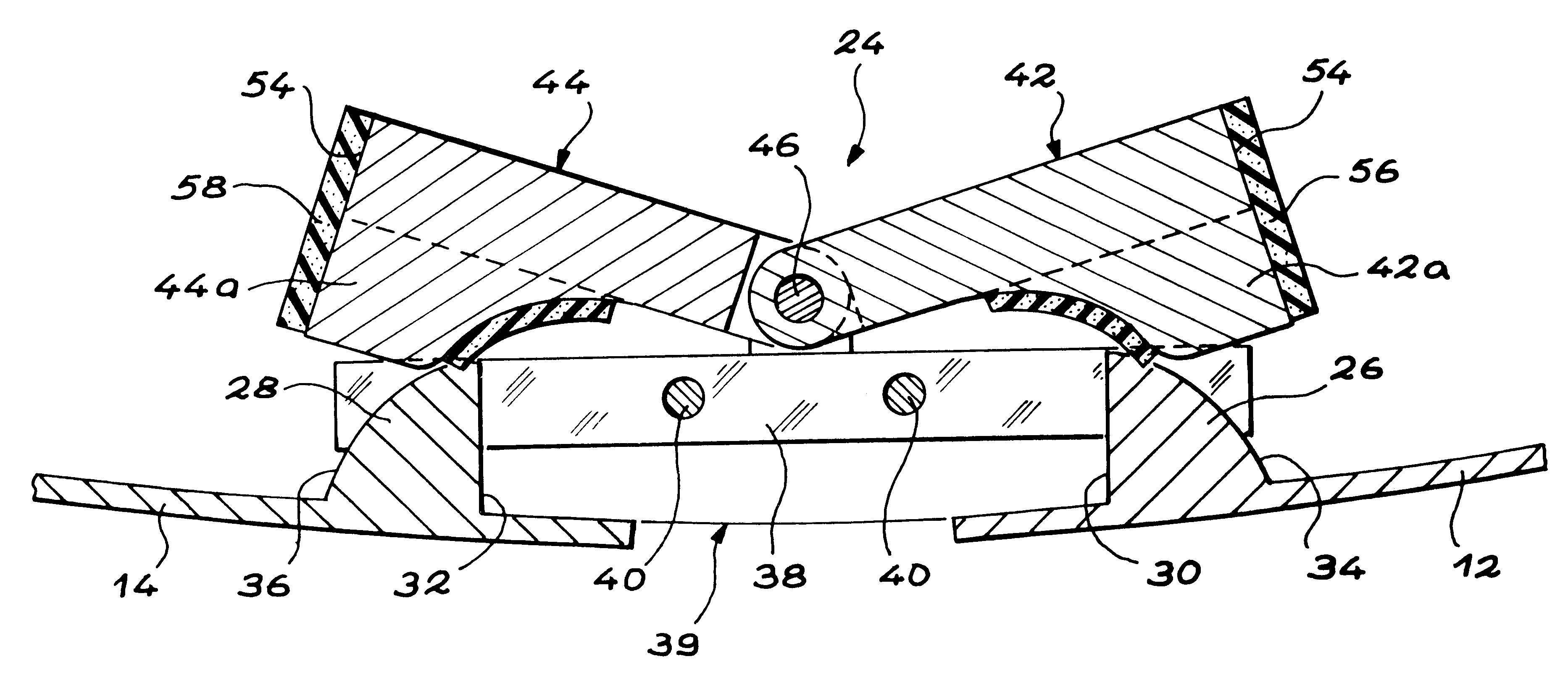
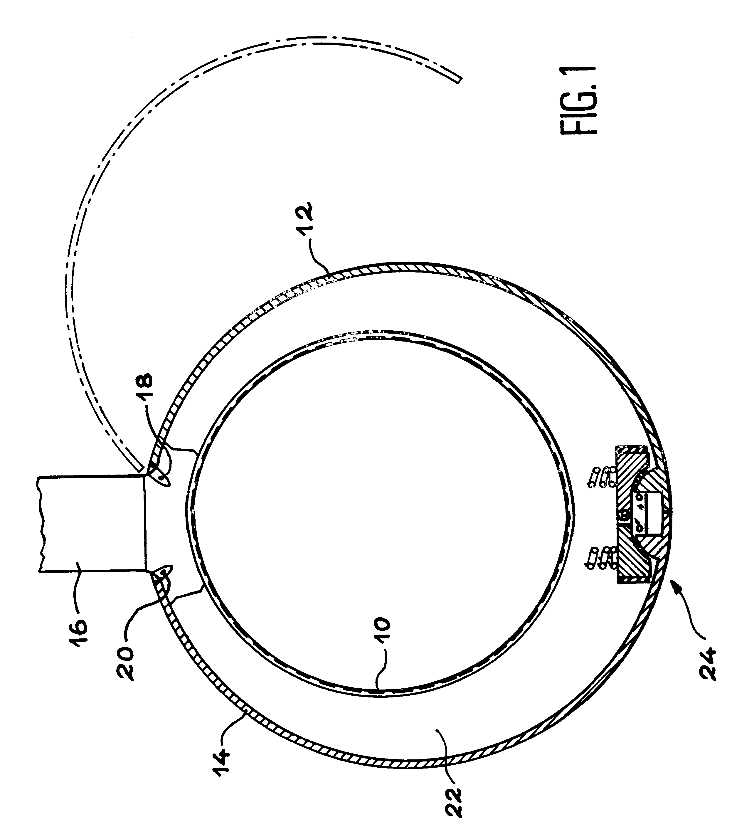
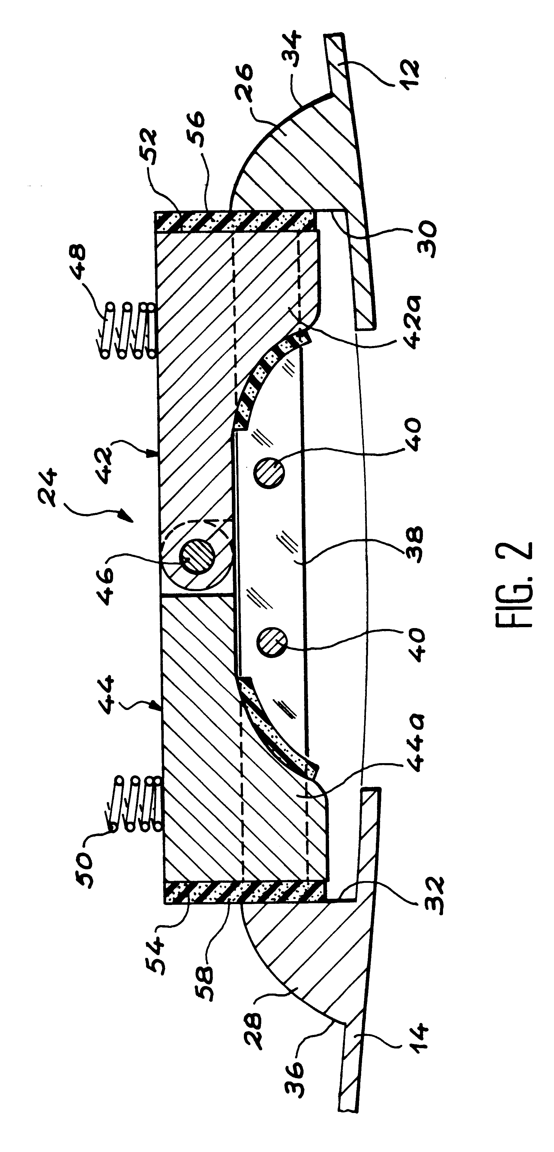
In order to avoid an operator forgetting to actuate locking mechanism interposed between two elements, such as the pod cowls (12, 14) of an aircraft engine, when said elements are in the closed position, use is made of a closure fault indicator. Said indicator comprises retractable abutment members (42, 44) automatically maintaining the two elements spaced from one another in a visible manner, when said elements are moved from their open position into their closed position.

Description

The invention relates to a closure fault indicator for locking means interposed between two elements able to occupy with respect to one another an open position and a closed position.Such an indicator can in particular be used on an aircraft engine for immediately informing ground personnel of a closure fault or shortcoming of locking means interposed between the pod cowls of said engine.PRIOR ARTAircraft engine pods are normally equipped with cowls, whose opening gives access, when the aircraft is on the ground, to various equipments, systems, etc. for maintaining the same. When the aircraft is in flight, the cowls are closed and have a shape such that they ensure the aerodynamic continuity of the complete engine.More specifically, the pod of a ducted turbofan engine is generally equipped with at least one pair of cowls, respectively to the right and left, which are placed around the engine fan. Each of the cowls has an approximately C-shaped cross-section in a transverse plane per...

Claims


Application Information

Patent Timeline
IPC IPC(8): B64D29/08B64D29/00E05B41/00
CPCE05B41/00B64D29/00Y10T292/0917
Inventor DE CARVALHO, ERICDELMAS, ERIC
Owner AEROSPATIALE MATRA AIRBUS
Learn More