Chair

a chair and backrest technology, applied in the field of chairs, can solve the problems of large rearward tilt of the upper back portion, concentrated sitting person, unstable sitting person,

Inactive Publication Date: 2003-12-30
KOKUYO CO LTD
View PDF10 Cites 64 Cited by
  • Summary
  • Abstract
  • Description
  • Claims
  • Application Information

AI Technical Summary

Benefits of technology

If the chair having the back portion divided into the upper back portion and the lower back portion is constructed to allow the upper back portion to incline rearwardly with the lower back portion being maintained at a predetermined angle, the chair allows the sitting person to bend his or her backbone backwardly thereby refreshing the sitting person.
In the case where the upper back portion is inclined rearwardly relative to the lower back portion, the distance between the upper back portion and the lower back portion changes. To absorb this change in the distance, it is preferred that an upholstery member be attached to a body contacting part of the back portion. The provision of such an upholstery member makes it possible not only to absorb changes in the distance between the upper back portion and the lower back portion but also to make the surface of the whole back portion smooth.

Problems solved by technology

With such a conventional construction having a shaft for rotation intermediate between the upper and lower parts of the backrest portion, however, the radius of gyration with which the upper back portion is inclined rearwardly is small and, hence, the upper end side of the upper back portion largely leans rearwardly.
Consequently, when the upper back portion thus constructed is inclined rearwardly, it cannot support the shoulders or parts therearound of the sitting person and, hence, this condition is substantially the same as the absence of the upper back portion, making the sitting person unstable.
Further, the provision of the shaft for rotation intermediate between the upper and lower parts of the backrest portion raises a problem that the load of the sitting person is concentrated on the shaft for rotation because the backrest portion steeply bends about the shaft, thus making the sitting person feel uncomfortable or giving him or her a sense of incongruity or the like.

Method used


Image

  • Chair
  • Chair
  • Chair

Examples


Embodiment Construction

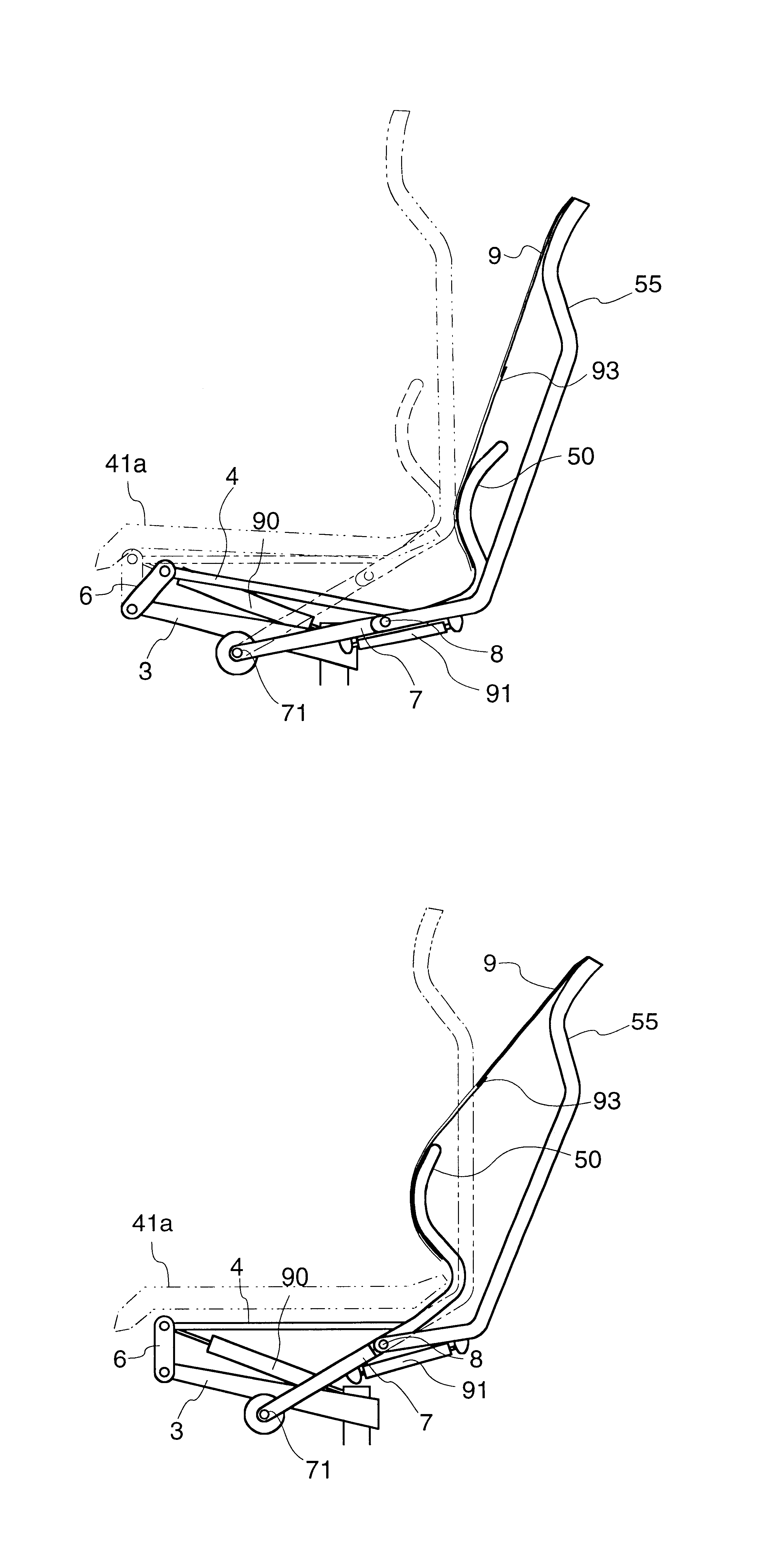
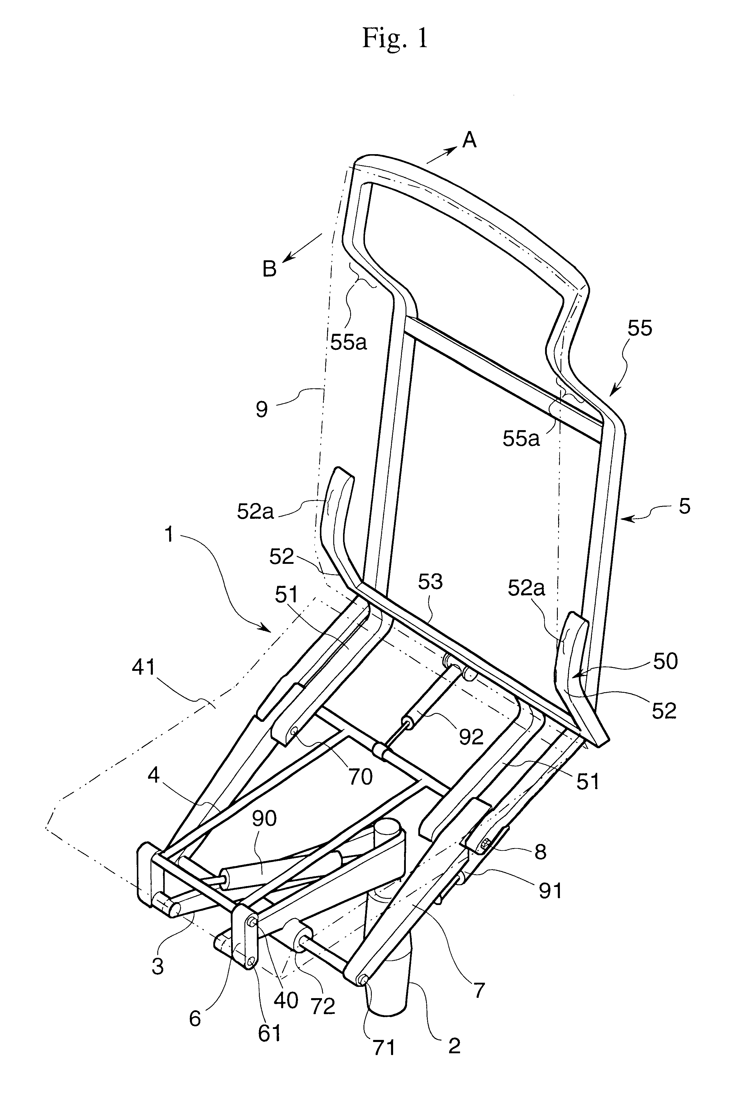
Hereinafter, one embodiment of the present invention will be described with reference to the drawings. FIG. 1 is a perspective view showing a principal part of a chair 1 representing one embodiment of the present invention. The chair 1 includes a support base 3 mounted on a base leg 2, links 6 and 7 attached to the support base 3, a seat frame 4 forming a seat portion and attached to the links 6 and 7, and a backrest frame 5 comprising a backrest upper frame 55 forming an upper back portion and a backrest lower frame 50 forming a lower back portion. The chair 1 further comprises an upholstery member 9 of cloth or the like mounted to extend between the backrest upper frame 55 and the backrest lower frame 50, and a seat cushion 41 having a seating surface 41a on the obverse side thereof and mounted on an upper portion of the seat frame 4.

The support base 3 is constructed of an aluminum member shaped into an inverted triangle and has a lower side attached to the base leg 2 and a front ...


PUM


Abstract

A chair wherein a backrest frame 5 located rearwardly of a seat frame 4 is divided into a backrest upper frame 55 and a backrest lower frame 50, at least the backrest upper frame 55 being capable of inclining rearwardly, is of a construction that shafts 8 and 71 for rearwardly inclining the backrest upper frame 55 are provided to allow the backrest upper frame 55 to incline rearwardly about one of the shafts 8 and 71. The chair of this construction is made more comfortable to sit.

Description

TECHNICAL FIELDThe present invention relates to chair structures and, more specifically, to a chair made more comfortable to sit.BACKGROUND ARTAmong chairs presently used in offices and the like, there exist chairs of the type which is capable of bending an upper portion of its back rearwardly. Such a chair, which allows the backbone of a person sitting thereon to bend backwardly thereby refreshing the sitting person, is generally of a construction having a shaft for rotation mounted intermediate between upper part and lower part of the backrest portion to allow a back portion above the shaft for rotation to incline rearwardly about the shaft for rotation.With such a conventional construction having a shaft for rotation intermediate between the upper and lower parts of the backrest portion, however, the radius of gyration with which the upper back portion is inclined rearwardly is small and, hence, the upper end side of the upper back portion largely leans rearwardly. Consequently, ...

Claims


Application Information

Patent Timeline
Patent Type & Authority Patents(United States)
IPC IPC(8): A47C7/36A47C7/38A47C1/024A47C1/022A47C4/00A47C3/026A47C7/46
CPCA47C1/03255A47C1/03283A47C7/46A47C7/405A47C7/38
Inventor KINOSHITA, YOJIROUEDA, NOBUYUKI
Owner KOKUYO CO LTD
Why Eureka
Try Eureka